Nissan Versa (N17): Shift control
SHIFT CONTROL : System Description
SYSTEM DIAGRAM
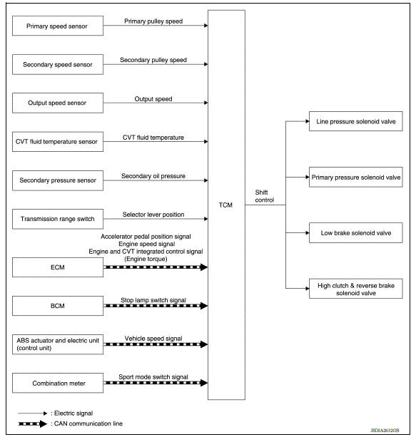
DESCRIPTION
To select the gear ratio that can give the driving force to meet driver's intent or vehicle situation, the vehicle driving condition such as vehicle speed or accelerator pedal position is detected and the most appropriate gear ratio is selected and the shifting method before reaching the speed is determined. The information is output to the primary pressure solenoid valve to control the line pressure input/output to the primary pulley, to determine the primary pulley (movable pulley) position and to control the gear position.
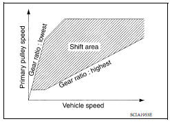
D Position (Normal)
Gear shifting is performed in all shifting ranges from the lowest to the highest gear ratio.
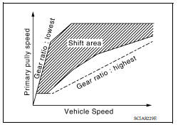
D Position (Sport)
The gear ratio is generally high by limiting the shifting range on the high side, and this always generates a large driving power.
L Position
By limiting the shifting range only to the lowest of the gear ratio, a large driving force and engine brake are obtained.

Hill Climbing And Descending Control
If a downhill is detected with the accelerator pedal is released, the system performs downshift to increase the engine brake force so that vehicle may not be accelerated more than necessary. If a climbing hill is detected, the system improves the acceleration performance in re-acceleration by limiting the gear shift range on the high side.
NOTE: For engine brake control on a downhill, the control can be stopped with CONSULT.

Control In Acceleration
From change of the vehicle speed or accelerator pedal position, the acceleration request level of the driver or driving scene is evaluated. In start or acceleration during driving, the gear shift characteristics with linearity of revolution increase and vehicle speed increase are gained to improve the acceleration feel.
SELECT CONTROL
SELECT CONTROL : System Description
SYSTEM DIAGRAM

DESCRIPTION
Based on accelerator pedal angle, engine speed, primary pulley speed, and the secondary pulley speed, the optimum operating pressure is set to reduce impact of a selector lever operation while shifting from "N" ("P") to "D" ("R") position.
 Line pressure control
LINE PRESSURE CONTROL : System Description SYSTEM DIAGRAM DESCRIPTION Highly accurate line pressure control (secondary pressure control) reduces friction for improvement of fuel economy. No ...
Lock-up control
LOCK-UP CONTROL : System Description SYSTEM DIAGRAM DESCRIPTION Controls for improvement of the transmission efficiency by engaging the torque converter clutch in the torque converter ...
Other materials:
Doors
When the doors are locked using one of the
following methods, the doors cannot be opened
using the inside or outside door handles. The
doors must be unlocked to open the doors.
WARNING
Before opening any door, always look
for and avoid oncoming traffic.
To help avoid risk of injury or de ...
P062F EEPROM
Description
TCM checks the value read in FLASH ROM at ignition switch ON, and judges if
there is writing failure to
FLASH ROM or malfunction of FLASH ROM.
DTC Logic
DTC DETECTION LOGIC
DTC
Trouble diagnosis name
DTC detection condition
Possible causes
P062F
Inter ...
Categories
- Manuals Home
- Nissan Versa Owners Manual
- Nissan Versa Service Manual
- Video Guides
- Questions & Answers
- External Resources
- Latest Updates
- Most Popular
- Sitemap
- Search the site
- Privacy Policy
- Contact Us

0.0052