Nissan Versa (N17): Rear drum brake
Exploded View

1. Shoe hold pin 2. Back plate 3. Plug
4. Brake shoe 5. Spring 6. Upper spring
7. Adjuster 8. Return spring 9. Brake drum
10. Boot 11. Piston 12. Piston cup
13. Spring 14. Wheel cylinder 15. Bleeder valve
16. Cap
 1: Apply rubber grease.
 2: Apply PBC (Poly Butyl Cuprysil)
grease or silicone-based grease.
2: Apply PBC (Poly Butyl Cuprysil)
grease or silicone-based grease.
 : Apply brake fluid
Removal and Installation
WARNING: Clean dust from brake drum and shoe assembly with a vacuum dust collector to minimize the hazard of air borne particles or other materials.
CAUTION:
- Do not depress the brake pedal while removing the brake drum because the pistons may pop out.
- Do not drop the removed parts.
- Do not spill or splash brake fluid on the brake drum.
NOTE: When removing components such as hoses, tubes/lines, etc., cap or plug openings to prevent fluid from spilling.
REMOVAL
- Remove the wheel and tire assemblies using power tool. Refer to WT "Adjustment".
- Drain the brake fluid when removing or disassembling the wheel cylinder is necessary. Refer to BR "Draining".
- Remove the brake drum. Refer to RAX "Exploded View".
NOTE:
- Make sure the parking brake lever is fully released prior to removal of the brake drum.
- The rear wheel hub is housed inside the brake drum.
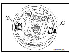
- Remove the springs (1) by pushing them inward toward the
vehicle and rotating, this will release the shoe hold pins, and the
brake shoe assembly (brake shoes, each spring, and adjuster).
CAUTION: Do not damage the boot of the wheel cylinder.
- Disconnect the parking brake cable from operating lever.
CAUTION: Do not bend the parking brake lever.
- Disassemble the brake shoe assembly (brake shoe, each spring, and adjuster).
- Remove the wheel cylinder with the following procedure.
a. Disconnect the brake tube from the wheel cylinder.
b. Remove the two bolts and the wheel cylinder from back plate.
8. Perform inspection after removal. Refer to BR "Inspection and Adjustment".
INSTALLATION
WARNING: Since dust covering the rear brake has an affect on human body, the dust must be removed with a dust collector. Do not splatter the dust with an air blow gun.
CAUTION:
- Do not depress the brake pedal while removing the brake drum.
- Do not drop the removed parts.
- Do not spill or splash brake fluid on the brake drum.
Note the following, and install in the reverse of removal.
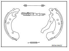
- Check the difference between left and right wheel of adjuster.
 : Front
- Shorten the length of the adjuster by rotating it.
- Apply PBC (Poly Butyl Cuprysil) silicone-based grease to the mating surfaces between the adjusters and the brake shoes.
- Apply PBC (Poly Butyl Cuprysil) silicone-based grease to the mating surfaces between the back plates and the brake shoes.
- Apply PBC (Poly Butyl Cuprysil) silicone-based grease to the mating surfaces between the wheel cylinders and brake shoes.
- Apply PBC (Poly Butyl Cuprysil) silicone-based grease to the mating surfaces between the brake shoe anchor areas and brake shoes.
- Do not damage the wheel cylinder.
- Check the component parts of drum brake assembly are installed properly.
- Check the brake shoe sliding surface and brake drum inner surface for grease. Make sure that grease does not contact the lining material.
- Perform the air bleeding when removed or disassembled the wheel cylinder. Refer to BR "Bleeding Brake System".
- Do not allow foreign matter (e.g. dust) and oils other than brake fluid to enter the reservoir tank.
- Adjust the brake shoe clearance (parking brake lever stroke) after install and air bleeding. Refer to PB "Inspection and Adjustment".

Disassembly and Assembly
DISASSEMBLY
- Remove the boot from wheel cylinder. Refer to BR "Exploded View".
- Remove the piston, piston cup and spring from wheel cylinder.
CAUTION: Pull the piston out from the wheel cylinder to prevent the wheel cylinder inner wall from being damaged.
- Remove piston cup from piston.
- Perform inspection after disassembly. Refer to BR "Inspection and Adjustment".
ASSEMBLY
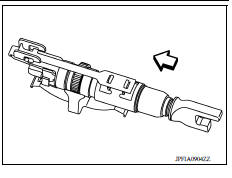
- Apply rubber grease to the piston cup (1) and boot (2).
- Install piston cup and boot to piston (3).
CAUTION:
- Do not mistake the direction.
- Do not reuse piston cup and boot.
- Apply new brake fluid to piston and wheel cylinder inner wall,
and install spring, piston cover, piston to wheel cylinder.
CAUTION: Do not damage the wheel cylinder inner wall.
- Install the boot to wheel cylinder. Refer to BR "Exploded View".
- Perform inspection after assembly. Refer to BR "Inspection and Adjustment".

Inspection and Adjustment
INSPECTION AFTER REMOVAL
Check the following items and replace if necessary.
- Check the brake lining for excessive wear, damage, and peeling.
- Check the brake shoe sliding surface for excessive wear and damage.
- Check each spring for settling, excessive wear, damage, and rust.
- Check the adjuster for smoothness, and check it for excessive wear, damage, and rust.
- Check the back plate for damage, cracks, and deformation.
- Check the wheel cylinder for cracks, damage, and leakage of brake fluid.
- Visually check the brake drum for excessive wear, cracks, and damage with a pair of vernier calipers.
- Check the drum brake component parts for excessive wear, damage, and rust.
INSPECTION AFTER DISASSEMBLY
Check the following items and replace if necessary.
- Check the wheel cylinder inner wall for excessive wear, cracks, and damage.
- Check the piston for excessive wear and damage.
INSPECTION AFTER ASSEMBLY
Check that the piston moves smoothly.
INSPECTION AFTER INSTALLATION
- Check that the component parts of drum brake assembly are installed properly.
- Rotate the brake drum and check that there is no drag. Perform the following procedure if necessary.
- Remove the brake shoe. Refer to BR "Removal and Installation".
- Push the piston.
CAUTION: Push both side of the piston simultaneously.
- Install the brake shoe. Refer to BR "Removal and Installation".
- Adjust the brake shoe clearance (parking brake lever stroke). Refer to PB "Inspection and Adjustment".
- Check a drag of rear drum brake again. If any drag is found, disassemble the wheel cylinder and replace if necessary. Refer to BR "Disassembly and Assembly".
- Burnish contact surface between brake lining and brake drum after refinishing or replacing brake lining or brake drum, or if a soft pedal occurs at very low mileage. Refer to BR "BRAKE LINING : Inspection and Adjustment" (brake lining), BR "BRAKE DRUM : Inspection and Adjustment" (brake drum).
ADJUSTMENT AFTER INSTALLATION
Adjust the brake shoe clearance (parking brake lever stroke). Refer to PB "Inspection and Adjustment".
SERVICE DATA AND SPECIFICATIONS (SDS)
General Specifications

Brake Pedal

Brake Booster

Front Disc Brake

Rear Drum Brake

 Brake caliper assembly
BRAKE CALIPER ASSEMBLY : Exploded View REMOVAL 1. Brake caliper assembly DISASSEMBLY 1. Cap 2. Bleeder valve 3. Cylinder body 4. Piston seal 5. Piston 6. Piston boot 7. Sliding pin 8. Slid ...
Precautions
Precaution for Supplemental Restraint System (SRS) "AIR BAG" and "SEAT BELT PRE-TENSIONER" The Supplemental Restraint System such as "AIR BAG" and "SEAT BELT PRE-TENSIONER", us ...
Other materials:
Key interlock cable
Exploded View
1. CVT shift selector assembly 2. Key interlock cable
A: Key cylinder B: Lock plate C: Clip
Removal and Installation
REMOVAL
CAUTION:
Always apply the parking brake before performing removal and installation.
Move the shift selector to the "N" position.
Remove the shi ...
Front
FRONT : Exploded View
1. Master cylinder brake pipe assembly
(front)
2. Master cylinder brake pipe assembly
(rear)
3. ABS actuator to connector brake
pipe assembly (RH)
4. ABS actuator to connector brake
pipe assembly (LH)
5. Brake pipe connector 6. Brake pipe assembly (RH front)
7. B ...
Categories
- Manuals Home
- Nissan Versa Owners Manual
- Nissan Versa Service Manual
- Video Guides
- Questions & Answers
- External Resources
- Latest Updates
- Most Popular
- Sitemap
- Search the site
- Privacy Policy
- Contact Us

0.0098