Nissan Versa (N17): Brake caliper assembly
BRAKE CALIPER ASSEMBLY : Exploded View
REMOVAL

1. Brake caliper assembly
DISASSEMBLY

1. Cap 2. Bleeder valve 3. Cylinder body
4. Piston seal 5. Piston 6. Piston boot
7. Sliding pin 8. Sliding pin boot 9. Bushing
10. Torque member  Apply rubber
grease
Apply rubber
grease  Apply brake fluid
NOTE: LH front brake caliper shown, RH front brake caliper similar.
Brake caliper assembly : Removal and Installation
WARNING: Clean dust on caliper and brake pad with a vacuum dust collector to minimize the hazard of air borne particles or other materials.
CAUTION:
- While removing caliper, do not depress the brake pedal because the piston will pop out.
- Do not damage piston boot.
- Do not spill or splash brake fluid on painted surfaces. Brake fluid may seriously damage paint. Wipe it out immediately and wash with water if it gets on a protect surface.
- Keep disc rotor free from brake fluid.
- Do not reuse drained brake fluid.
NOTE: When removing components such as hoses, tubes/lines, etc., cap or plug openings to prevent fluid from spilling.
REMOVAL
- Remove the front wheel and tire assemblies using power tool. Refer to WT "Adjustment".
- Drain brake fluid. Refer to BR "Draining".
- Remove union bolt and disconnect brake hose from caliper assembly.
Discard the copper sealing washers.
CAUTION: Do not reuse copper sealing washers.
- Remove torque member bolts, and remove brake caliper assembly.
CAUTION: Do not drop brake pad and caliper assembly.
- Remove disc rotor. If reusing the disc rotor, apply matching marks on
the wheel hub and rotor do aid with
installation.
CAUTION: Put matching marks on wheel hub assembly and disc rotor, if it is necessary to remove disc rotor.
INSTALLATION
- Install disc rotor, align the matching marks if installing the original
disc rotor.
CAUTION: Align the marks on disc rotor and wheel hub at the time of installation when reusing disc rotor.
- Install the brake caliper assembly to the steering knuckle and tighten
the torque member bolts to the specified
torque.
CAUTION: Do not allow oil or any moisture on all contact surfaces between steering knuckle and caliper assembly, bolts and washer.
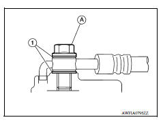
- Install brake hose to brake caliper assembly with new copper sealing washers (1). Tighten union bolt (A) to the specified torque. Refer to BR "FRONT : Exploded View".
CAUTION:
- Do not reuse copper sealing washers (1).
- Union bolt (A).
- Refill with new brake fluid and bleed air from the brake hydraulic system. Refer to BR "Bleeding Brake System".
- Check front disc brakes for drag.
- Install the front wheel and tire assemblies. Refer to WT "Adjustment".
Brake caliper assembly : Disassembly and Assembly
DISASSEMBLY
NOTE: Do not remove the torque member, pad return springs, brake pads and pad retainers when disassembling and assembling the brake caliper assembly.
- Place a wooden block as shown, and blow air from union bolt
mounting hole to remove piston and piston boot.
WARNING: Do not get fingers caught between the piston and wooden block.

2. Remove piston seal from cylinder body using suitable tool.
CAUTION:
- Be careful not to damage a cylinder inner wall.
- Do not reuse piston seal.
3. Remove bleeder valve and cap.
4. Perform inspection after disassembly.

INSPECTION AFTER DISASSEMBLY
Caliper
Check the inner wall of caliper for corrosion, wear, and damage. Replace as necessary.
CAUTION: Clean the caliper using new brake fluid. Do not use mineral oils such as gasoline or kerosene.
Torque Member
Check torque member for wear, cracks, and damage. Replace as necessary.
Piston
Check the piston surface for corrosion, wear, and damage. Replace as necessary.
CAUTION: The piston sliding surface is plated. Do not polish with sandpaper.
Sliding Pin Bolt, Sliding Pin Boot
Check the sliding pin, sliding pin bolt, and sliding pin boot for wear, damage, and cracks. Replace as necessary.
ASSEMBLY
- Install bleeder valve and cap.
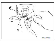
- Apply brake fluid to piston seal (1), and install to groove in cylinder body.
CAUTION: Do not reuse piston seal.
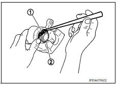
3. Apply rubber grease to piston boot (1). Cover the piston (2) end with piston boot, and then install cylinder side lip on piston boot securely into a groove on cylinder body.
CAUTION: Do not reuse piston boot.
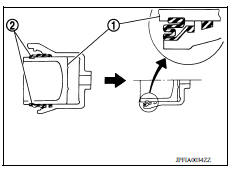
4. Push piston (1) into cylinder body by hand and push piston boot (2) piston-side lip into the piston groove.
CAUTION: Press the piston evenly and vary the pressing point to prevent cylinder inner wall from being rubbed.
 Brake pad
BRAKE PAD : Exploded View 1. Cylinder body 2. Inner shim 3. Inner pad (with pad wear sensor) 4. Pad return spring 5. Pad retainer 6. Torque member 7. Outer pad 8. Outer shim : Apply MOLYKOTE 7 ...
Rear drum brake
Exploded View 1. Shoe hold pin 2. Back plate 3. Plug 4. Brake shoe 5. Spring 6. Upper spring 7. Adjuster 8. Return spring 9. Brake drum 10. Boot 11. Piston 12. Piston cup 13. Spring 14. Wheel ...
Other materials:
Recommended fluids/lubricants and capacities
The following are approximate capacities. The actual refill capacities may
be a little different. When refilling, follow the procedure
described in the "Do-it-yourself" section to determine the proper refill
capacity.
...
Transverse link
Exploded View
1. Front suspension member 2. Transverse link
Removal and Installation
REMOVAL
Remove the wheel and tire assembly using power tool. Refer to WT
"Adjustment".
Remove transverse link from steering knuckle. Refer to FAX "Exploded
View".
Remove tr ...
Categories
- Manuals Home
- Nissan Versa Owners Manual
- Nissan Versa Service Manual
- Video Guides
- Questions & Answers
- External Resources
- Latest Updates
- Most Popular
- Sitemap
- Search the site
- Privacy Policy
- Contact Us

0.0099