Nissan Versa (N17): Precaution
Precaution for Supplemental Restraint System (SRS) "AIR BAG" and "SEAT BELT PRETENSIONER"
The Supplemental Restraint System such as "AIR BAG" and "SEAT BELT PRETENSIONER", used along with a front seat belt, helps to reduce the risk or severity of injury to the driver and front passenger for certain types of collision. This system includes seat belt switch inputs and dual stage front air bag modules. The SRS system uses the seat belt switches to determine the front air bag deployment, and may only deploy one front air bag, depending on the severity of a collision and whether the front occupants are belted or unbelted.
Information necessary to service the system safely is included in the SR and SB section of this Service Manual.
WARNING:
- To avoid rendering the SRS inoperative, which could increase the risk of personal injury or death in the event of a collision which would result in air bag inflation, all maintenance must be performed by an authorized NISSAN/INFINITI dealer.
- Improper maintenance, including incorrect removal and installation of the SRS, can lead to personal injury caused by unintentional activation of the system. For removal of Spiral Cable and Air Bag Module, see the SR section.
- Do not use electrical test equipment on any circuit related to the SRS unless instructed to in this Service Manual. SRS wiring harnesses can be identified by yellow and/or orange harnesses or harness connectors.
PRECAUTIONS WHEN USING POWER TOOLS (AIR OR ELECTRIC) AND HAMMERS
WARNING:
- When working near the Airbag Diagnosis Sensor Unit or other Airbag System sensors with the Ignition ON or engine running, DO NOT use air or electric power tools or strike near the sensor(s) with a hammer. Heavy vibration could activate the sensor(s) and deploy the air bag(s), possibly causing serious injury.
- When using air or electric power tools or hammers, always switch the Ignition OFF, disconnect the battery and wait at least three minutes before performing any service.
Precaution for Procedure without Cowl Top Cover
When performing the procedure after removing cowl top cover, cover the lower end of windshield with urethane, etc to prevent damage to windshield.

On Board Diagnostic (OBD) System of Engine and A/T or CVT
The ECM has an on board diagnostic system. It will light up the malfunction indicator lamp (MIL) to warn the driver of a malfunction causing emission deterioration.
CAUTION:
- Be sure to turn the ignition switch OFF and disconnect the negative battery cable before any repair or inspection work. The open/short circuit of related switches, sensors, solenoid valves, etc. will cause the MIL to light up.
- Be sure to connect and lock the connectors securely after work. A loose (unlocked) connector will cause the MIL to light up due to the open circuit. (Be sure the connector is free from water, grease, dirt, bent terminals, etc.)
- Certain systems and components, especially those related to OBD, may use a new style slidelocking type harness connector.
- Be sure to route and secure the harnesses properly after work. The interference of the harness with a bracket, etc. may cause the MIL to light up due to the short circuit.
- Be sure to connect rubber tubes properly after work. A misconnected or disconnected rubber tube may cause the MIL to light up due to the malfunction of the fuel injection system, etc.
- Be sure to erase the unnecessary malfunction information (repairs completed) from the ECM and TCM (Transmission control module) before returning the vehicle to the customer.
General Precautions
- Always use a 12 volt battery as power source.
- Do not attempt to disconnect battery cables while engine is running.
- Before connecting or disconnecting the ECM harness connector, turn ignition switch OFF and disconnect negative battery cable. Failure to do so may damage the ECM because battery voltage is applied to ECM even if ignition switch is turned OFF.
- Before removing parts, turn ignition switch OFF and then disconnect battery ground cable.

- Do not disassemble ECM.
- If a battery cable is disconnected, the memory will return to
the ECM value.
The ECM will now start to selfcontrol at its initial value. So, engine operation can vary slightly in this case. However, this is not an indication of a malfunction. Do not replace parts because of a slight variation.
- If the battery is disconnected, the following emissionrelated diagnostic information will be lost within 24 hours.
- Diagnostic trouble codes
- 1st trip diagnostic trouble codes
- Freeze frame data
- 1st trip freeze frame data
- System readiness test (SRT) codes
- Test values

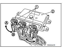
- When connecting ECM harness connector (1), fasten (B) it securely with a lever as far as it will go as shown in the figure.
- ECM (2)
- Loosen (A)
- When connecting or disconnecting pin connectors into or
from ECM, take care not to damage pin terminals (bend or
break).
Make sure that there are not any bends or breaks on ECM pin terminal, when connecting pin connectors.
- Securely connect ECM harness connectors.
A poor connection can cause an extremely high (surge) voltage to develop in coil and condenser, thus resulting in damage to ICs.
- Keep engine control system harness at least 10 cm (4 in) away from adjacent harness, to prevent engine control system malfunctions due to receiving external noise, degraded operation of ICs, etc.

- Keep engine control system parts and harness dry.
- Before replacing ECM, perform ECM Terminals and Reference Value inspection and make sure ECM functions properly.
- Handle mass air flow sensor carefully to avoid damage.
- Do not clean mass air flow sensor with any type of detergent.
- Do not disassemble electric throttle control actuator.
- Even a slight leak in the air intake system can cause serious incidents.
- Do not shock or jar the camshaft position sensor (PHASE), crankshaft position sensor (POS).

- After performing each TROUBLE DIAGNOSIS, perform DTC CONFIRMATION PROCEDURE or Component Function Check. The DTC should not be displayed in the DTC Confirmation Procedure if the repair is completed. The Component Function Check should be a good result if the repair is completed.

- When measuring ECM signals with a circuit tester, never allow
the two tester probes to contact.
Accidental contact of probes will cause a short circuit and damage the ECM power transistor.

- Do not operate fuel pump when there is no fuel in lines.
- Tighten fuel hose clamps to the specified torque.
- Do not depress accelerator pedal when starting.
- Immediately after starting, do not rev up engine unnecessarily.
- Do not rev up engine just prior to shutdown.
- When installing C.B. ham radio or a mobile phone, be sure to observe the following as it may adversely affect electronic control systems depending on installation location.
- Keep the antenna as far as possible from the electronic control units.
- Keep the antenna feeder line more than 20 cm (8 in) away from the harness of electronic controls.
Do not let them run parallel for a long distance.
- Adjust the antenna and feeder line so that the standingwave ratio can be kept smaller.
- Be sure to ground the radio to vehicle body.

PREPARATION
Special Service Tools
NOTE:
The actual shapes of KentMoore tools may differ from those of special service tools illustrated here.
| Tool number (KentMoore No.) Tool name | Description |
(J44321)
Fuel pressure gauge kit
 |
Checks fuel pressure |
(J443216)
Fuel pressure adapter
 |
Connects fuel pressure gauge to quick connector type fuel lines. |
KV10118400
Fuel tube adapter
 |
Measuring fuel pressure |
KV10120000
Fuel tube adapter
 |
Commercial Service Tools
| Tool name (KentMoore No.) | Description |
Leak detector
i.e.: (J41416)
 |
Locates the EVAP leak |
EVAP service port adapter
i.e.: (J41413OBD)
 |
Applies positive pressure through EVAP service port |
Fuel filler cap adapter
i.e.: (MLR8382)
 |
Checks fuel tank vacuum relief valve opening pressure |
Socket wrench
 |
Removes and installs engine coolant temperature sensor |
Oxygen sensor thread cleaner
i.e.: (J4389718), (J4389712)
 |
Reconditioning the exhaust system threads before installing
a new oxygen sensor. Use with antiseize lubricant
shown below.
a: 18 mm diameter with pitch 1.5 mm for Zirconia Oxygen Sensor b: 12 mm diameter with pitch 1.25 mm for Titania Oxygen Sensor |
Antiseize lubricant
i.e.: (PermatexTM 133AR or
equivalent meeting MIL specification
MILA907)
 |
Lubricating oxygen sensor thread cleaning tool when reconditioning exhaust system threads. |
 Water outlet
Exploded View M/T models 1. Engine coolant temperature sensor 2. Clamp 3. Gasket 4. Clamp 5. Bracket 6. Clamp 7. Water outlet 8. Clamp 9. Clamp 10. Cylinder block heater (Canada) A. From elect ...
Engine control system
ENGINE CONTROL SYSTEM : Component Parts Location 1. Mass air flow sensor (with intake air temperature sensor) 2. Electric throttle control actuator (with built in throttle position sensor an ...
Other materials:
Child safety
WARNING
Do not allow children to play with the seat
belts. Most seating positions are
equipped with Automatic Locking Retractor
(ALR) mode seat belts. If the seat belt
becomes wrapped around a child's neck
with the ALR mode activated, the child can
be seriously injured or killed if the seat
...
Precaution
Precaution for Supplemental Restraint System
(SRS) "AIR BAG" and "SEAT BELT PRETENSIONER"
The Supplemental Restraint System such as "AIR BAG" and "SEAT BELT
PRETENSIONER", used along
with a front seat belt, helps to reduce the risk or severity of injury to the
driver and f ...
Categories
- Manuals Home
- Nissan Versa Owners Manual
- Nissan Versa Service Manual
- Video Guides
- Questions & Answers
- External Resources
- Latest Updates
- Most Popular
- Sitemap
- Search the site
- Privacy Policy
- Contact Us

0.0111