Nissan Versa (N17): Engine control system
ENGINE CONTROL SYSTEM : Component Parts Location

1. Mass air flow sensor (with intake air temperature sensor) 2. Electric throttle control actuator (with built in throttle position sensor and throttle control motor) 3. EVAP canister purge volume control solenoid valve 4. Cooling fan motor 5. Refrigerant pressure sensor 6. Battery current sensor (with built in battery temperature sensor*1)*2 7. ECM 8. IPDM E/R
*1 : Not used *2 : CVT models

1. Ignition coil No.4 (with power transistor) 2. Ignition coil No.3 (with power transistor) 3. Ignition coil No.2 (with power transistor) 4. Ignition coil No.1 (with power transistor) 5. PCV valve 6. Intake valve timing control solenoid valve 7. Engine oil pressure sensor 8. Engine oil temperature sensor 9. Knock sensor 10. Engine coolant temperature sensor 11. Intake camshaft position sensor 12. Exhaust camshaft position sensor 13. Exhaust valve timing control solenoid valve 14. Fuel injector No.1 (Front) 15. Fuel injector No.1 (Rear) 16. Fuel injector No.2 (Front) 17. Fuel injector No.2 (Rear) 18. Fuel injector No.3 (Front) 19. Fuel injector No.3 (Rear) 20. Fuel injector No.4 (Front) 21. Fuel injector No.4 (Rear) 22. Crankshaft position sensor A. Engine front right side B. Left view of the engine C. Engine rear right side

1. A/F sensor 1 2. Heated oxygen sensor 2

1. ASCD steering switch 2. Fuel pump (with fuel level sensor unit
and fuel pressure regulator)
3. EVAP control system pressure sensor
4. EVAP canister 5. EVAP canister vent control valve 6. Clutch pedal position
switch
7. Stop lamp switch 8. Brake pedal position switch 9. Accelerator pedal position
sensor
A. Spare tire housing left side B. Periphery of pedals
 : Vehicle front
ENGINE CONTROL SYSTEM : Component Description
|
Component |
| ECM |
| A/F sensor 1 |
| A/F sensor 1 heater |
| Accelerator pedal position sensor |
| Battery current sensor |
| Clutch pedal position switch |
| Cooling fan motor |
| Crankshaft position sensor |
| Electric throttle control actuator |
| Engine coolant temperature sensor |
| Engine oil pressure sensor |
| Engine oil temperature sensor |
| EVAP canister purge volume control solenoid valve |
| EVAP canister vent control valve |
| EVAP control system pressure sensor |
| Exhaust camshaft position sensor |
| Exhaust valve timing control solenoid valve |
| Fuel injector |
| Fuel pump |
| Heated oxygen sensor 2 |
| Heated oxygen sensor 2 heater |
| Ignition coil (with power transistor) |
| Intake air temperature sensor |
| Intake camshaft position sensor |
| Intake valve timing control solenoid valve |
| Knock sensor |
| Mass air flow sensor |
| PCV valve |
| Refrigerant pressure senso |
| Stop lamp switch |
| Throttle control motor |
| Throttle control motor relay |
| Throttle position sensor |
| ASCD steering switch |
| Brake pedal position switch |
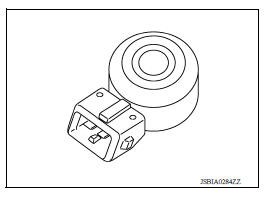
Accelerator Pedal Position Sensor
The accelerator pedal position sensor is installed on the upper end of the accelerator pedal assembly. The sensor detects the accelerator position and sends a signal to the ECM.
Accelerator pedal position sensor has two sensors. These sensors are a kind of potentiometer which transform the accelerator pedal position into output voltage, and emit the voltage signals to the ECM.
The ECM judges the current opening angle of the accelerator pedal from these signals and controls the throttle control motor based on these signals.
Idle position of the accelerator pedal is determined by the ECM receiving the signal from the accelerator pedal position sensor. The ECM uses this signal for the engine operation such as fuel cut.

Air Fuel Ratio Sensor 1
The air fuel ratio (A/F) sensor 1 is a planar onecell limit current sensor.
The sensor element of the A/F sensor 1 is composed an electrode layer, which transports ions. It has a heater in the element.
The sensor is capable of precise measurement
 = 1, but also in the
lean and rich range. Together with its control electronics, the sensor
outputs a clear, continuous signal throughout a wide
= 1, but also in the
lean and rich range. Together with its control electronics, the sensor
outputs a clear, continuous signal throughout a wide
 range.
The exhaust gas components diffuse through the diffusion layer at the sensor cell. An electrode layer is applied voltage, and this current relative oxygen density in lean. Also this current relative hydrocarbon density in rich.

Therefore, the A/F sensor 1 is able to indicate air fuel ratio by this electrode layer of current. In addition, a heater is integrated in the sensor to ensure the required operating temperature of about 800C (1,472F).
Air Fuel Ratio Sensor 1 Heater
SYSTEM DESCRIPTION
| Sensor | Input Signal to ECM | ECM function | Actuator |
| Camshaft position sensor (PHASE) Crankshaft position sensor (POS) | Engine speed | Air fuel ratio (A/F) sensor 1 heater control | Air fuel ratio (A/F) sensor 1 heater |
| Mass air flow sensor | Amount of intake air |
The ECM performs ON/OFF duty control of the A/F sensor 1 heater corresponding to the engine operating condition to keep the temperature of A/F sensor 1 element within the specified range.
Battery Current Sensor
The battery current sensor is installed to the battery cable at the negative terminal. The sensor measures the charging/discharging current of the battery.
The power generation voltage variable control enables fuel consumption to be decreased by reducing the engine load which is caused by the power generation of the generator.
Based on sensor signals, ECM judges whether or not the power generation voltage variable control is performed. When performing the power generation voltage variable control, ECM calculates the target power generation voltage based on the sensor signal. And ECM sends the calculated value as the power generation command value to IPDM E/R.

CAUTION:
Never connect the electrical component or the ground wire directly to the battery terminal. The connection causes the malfunction of the power generation voltage variable control, and then the battery discharge may occur.
Camshaft Position Sensor
The camshaft position sensor senses the protrusion of camshaft to identify a particular cylinder. The camshaft position sensor senses the piston position.
When the crankshaft position sensor system becomes inoperative, the camshaft position sensor provides various controls of engine parts instead, utilizing timing of cylinder identification signals.
The sensor consists of a permanent magnet and Hall IC.
When engine is running, the high and low parts of the teeth cause the gap with the sensor to change.
The changing gap causes the magnetic field near the sensor to change.
Due to the changing magnetic field, the voltage from the sensor changes.
ECM receives the signals as shown in the figure.


Clutch Pedal Position Switch
When the clutch pedal is depressed, the clutch pedal position switch turns ON and the clutch pedal position switch signal is sent to the ECM. The ECM judges the clutch pedal conditions via the signal (ON or OFF).
Cooling Fan
Cooling fan operates at low and high speed when the current flows in the cooling fan motor.
Crankshaft Position Sensor
The crankshaft position sensor is located on the cylinder block rear housing facing the gear teeth (cogs) of the signal plate at end of the crankshaft. It detects the fluctuation of the engine revolution.
The sensor consists of a permanent magnet and Hall IC.
When the engine is running, the high and low parts of the teeth cause the gap with the sensor to change.
The changing gap causes the magnetic field near the sensor to change.
Due to the changing magnetic field, the voltage from the sensor changes.
The ECM receives the voltage signal and detects the fluctuation of the engine revolution.
ECM receives the signals as shown in the figure.


ECM
The ECM consists of a microcomputer and connectors for signal input and output and for power supply. The ECM controls the engine.

Electric Throttle Control Actuator
Electric throttle control actuator consists of throttle control motor, throttle position sensor, etc.
The throttle control motor is operated by the ECM and it opens and closes the throttle valve.
The current opening angle of the throttle valve is detected by the throttle position sensor and it provides feedback to the ECM to control the throttle valve in response to driving conditions via the throttle control motor.
Engine Coolant Temperature Sensor
The engine coolant temperature sensor is used to detect the engine coolant temperature. The sensor modifies a voltage signal from the ECM. The modified signal returns to the ECM as the engine coolant temperature input. The sensor uses a thermistor which is sensitive to the change in temperature. The electrical resistance of the thermistor decreases as temperature increases.

<Reference data>
| Engine coolant temperature [C (F)] | Voltage* (V) | Resistance (kΩ) |
| -10 (14) | 4.4 | 7.0 11.4 |
| 20 (68) | 3.5 | 2.10 2.90 |
| 50 (122) | 2.2 | 0.68 1.00 |
| 90 (194) | 0.9 | 0.236 0.260 |
*: These data are reference values and are measured between ECM terminals.

Engine Oil Pressure Sensor
The engine oil pressure (EOP) sensor is detects engine oil pressure and transmits a voltage signal to the ECM.

Engine Oil Temperature Sensor
The engine oil temperature sensor is used to detect the engine oil temperature. The sensor modifies a voltage signal from the ECM.
The modified signal returns to the ECM as the engine oil temperature input. The sensor uses a thermistor which is sensitive to the change in temperature. The electrical resistance of the thermistor decreases as temperature increases.
<Reference data>
| Engine oil temperature [C (F)] | Voltage* (V) | Resistance (kΩ) |
| -10 (14) | 4.4 | 7.0 11.4 |
| 20 (68) | 3.5 | 2.10 2.90 |
| 50 (122) | 2.2 | 0.68 1.00 |
| 90 (194) | 0.9 | 0.236 0.260 |
| 110 (230) | 0.6 | 0.143 0.153 |
*: These data are reference values and are measured between ECM terminals.

EVAP Canister Purge Volume Control Solenoid Valve
The EVAP canister purge volume control solenoid valve uses a ON/ OFF duty to control the flow rate of fuel vapor from the EVAP canister.
The EVAP canister purge volume control solenoid valve is moved by ON/OFF pulses from the ECM. The longer the ON pulse, the greater the amount of fuel vapor that will flow through the valve.

EVAP Canister Vent Control Valve
The EVAP canister vent control valve is located on the EVAP canister and is used to seal the canister vent.
This solenoid valve responds to signals from the ECM. When the ECM sends an ON signal, the coil in the solenoid valve is energized.
A plunger will then move to seal the canister vent. The ability to seal the vent is necessary for the on board diagnosis of other evaporative emission control system components.
This solenoid valve is used only for diagnosis, and usually remains opened.
When the vent is closed, under normal purge conditions, the evaporative emission control system is depressurized and allows "EVAP Control System" diagnosis.

EVAP Control System Pressure Sensor
The EVAP control system pressure sensor detects pressure in the purge line. The sensor output voltage to the ECM increases as pressure increases.

Exhaust Valve Timing Control Solenoid Valve
Exhaust valve timing control solenoid valve is activated by ON/OFF pulse duty (ratio) signals from the ECM.
The exhaust valve timing control solenoid valve changes the oil amount and direction of flow through exhaust valve timing control unit or stops oil flow.
The longer pulse width retards valve angle.
The shorter pulse width advances valve angle.
When ON and OFF pulse widths become equal, the solenoid valve stops oil pressure flow to fix the exhaust valve angle at the control position.

Fuel Injector
The fuel injector is a small, precise solenoid valve. When the ECM supplies a ground to the fuel injector circuit, the coil in the fuel injector is energized. The energized coil pulls the ball valve back and allows fuel to flow through the fuel injector into the intake manifold.
The amount of fuel injected depends upon the injection pulse duration.
Pulse duration is the length of time the fuel injector remains open. The ECM controls the injection pulse duration based on engine fuel needs.

Fuel Pump
| Sensor | Input signal to ECM | ECM function | Actuator |
| Crankshaft position sensor (POS) Camshaft position sensor (PHASE) | Engine speed* | Fuel pump control | Fuel pump relay ↓ Fuel pump |
| Battery | Battery voltage* |
*: ECM determines the start signal status by the signals of engine speed and battery voltage.
The ECM activates the fuel pump for a few seconds after the ignition switch is turned ON to improve engine start ability. If the ECM receives a engine speed signal from the crankshaft position sensor (POS) and camshaft position sensor (PHASE), it knows that the engine is rotating, and causes the pump to operate. If the engine speed signal is not received when the ignition switch is ON, the engine stalls. The ECM stops pump operation and prevents battery discharging, thereby improving safety. The ECM does not directly drive the fuel pump. It controls the ON/OFF fuel pump relay, which in turn controls the fuel pump.
| Condition | Fuel pump operation |
| Ignition switch is turned to ON. | Operates for 1 second. |
| Engine running and cranking | Operates. |
| When engine is stopped | Stops in 1.5 seconds. |
| Except as shown above | Stops. |
Heated Oxygen Sensor 2
The heated oxygen sensor 2, after three way catalyst (manifold), monitors the oxygen level in the exhaust gas.
Even if switching characteristics of the air fuel ratio (A/F) sensor 1 are shifted, the airfuel ratio is controlled to stoichiometric, by the signal from the heated oxygen sensor 2.
This sensor is made of ceramic zirconia. The zirconia generates voltage from approximately 1 V in richer conditions to 0 V in leaner conditions.
Under normal conditions the heated oxygen sensor 2 is not used for engine control operation.

Heated Oxygen Sensor 2 Heater
SYSTEM DESCRIPTION
| Sensor | Input signal to ECM | ECM function | Actuator |
| Camshaft position sensor (PHASE) Crankshaft position sensor (POS) | Engine speed | Heated oxygen sensor 2 heater control | Heated oxygen sensor 2 heater |
| Engine coolant temperature sensor | Engine coolant temperature | ||
| Mass air flow sensor | Amount of intake air |
The ECM performs ON/OFF control of the heated oxygen sensor 2 heater corresponding to the engine speed, amount of intake air and engine coolant temperature.
OPERATION
| Engine speed | Heated oxygen sensor 2 heater |
| Above 3,600 rpm | OFF |
Below 3,600 rpm after the following conditions are met.
|
ON |
Ignition Coil With Power Transistor
The ignition signal from the ECM is sent to and amplified by the power transistor. The power transistor turns ON and OFF the ignition coil primary circuit. This ON/OFF operation induces the proper high voltage in the coil secondary circuit.
Intake Air Temperature Sensor
The intake air temperature sensor is builtinto mass air flow sensor (1). The sensor detects intake air temperature and transmits a signal to the ECM.
The temperature sensing unit uses a thermistor which is sensitive to the change in temperature. Electrical resistance of the thermistor decreases in response to the temperature rise.
<Reference data>
| Intake air temperature [C (F)] | Voltage* (V) | Resistance (kΩ) |
| 25 (77) | 3.3 | 1.800 2.200 |
| 80 (176) | 1.2 | 0.283 0.359 |
*: These data are reference values and are measured between ECM terminals.
Intake Valve Timing Control Solenoid Valve
Intake valve timing control solenoid valve is activated by ON/OFF pulse duty (ratio) signals from the ECM.
The intake valve timing control solenoid valve changes the oil amount and direction of flow through intake valve timing control unit or stops oil flow.
The longer pulse width advances valve angle.
The shorter pulse width retards valve angle.
When ON and OFF pulse widths become equal, the solenoid valve stops oil pressure flow to fix the intake valve angle at the control position.

Knock Sensor
The knock sensor is attached to the cylinder block. It senses engine knocking using a piezoelectric element. A knocking vibration from the cylinder block is sensed as vibrational pressure. This pressure is converted into a voltage signal and sent to the ECM.
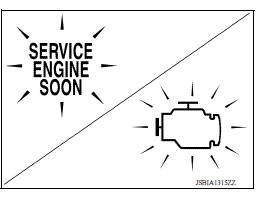
Malfunction Indicator Lamp (MIL)
The MIL is located on the combination meter.
The MIL will illuminate when the ignition switch is turned ON without the engine running. This is a bulb check.
When the engine is started, the MIL should turn OFF. If MIL remains ON or continues blinking, the on board diagnostic system detects a DTC(s) that affects exhaust gas.
Mass Air Flow Sensor
The mass air flow sensor (1) is placed in the stream of intake air. It measures the intake flow rate by measuring a part of the entire intake flow. The mass air flow sensor controls the temperature of the hot wire to a certain amount. The heat generated by the hot wire is reduced as the intake air flows around it. The more air, the greater the heat loss.
Therefore, the electric current supplied to hot wire is changed to maintain the temperature of the hot wire as air flow increases. The ECM detects the air flow by means of this current change.

Oil Pressure Warning Lamp
Oil pressure warning lamp is located on the combination meter.
It indicates the low pressure of the engine oil and the malfunction of the engine oil pressure system.
Combination meter turns the oil pressure warning lamp ON/OFF according to the oil pressure warning lamp signal received from ECM via CAN communication.

Refrigerant Pressure Sensor
The refrigerant pressure sensor is installed at the condenser of the air conditioner system. The sensor uses an electrostatic volume pressure transducer to convert refrigerant pressure to voltage. The voltage signal is sent to ECM, and ECM controls cooling fan system.

Stop Lamp Switch & Brake Pedal Position Switch
Stop lamp switch and brake pedal position switch are installed to brake pedal bracket.
ECM detects the state of the brake pedal by those two types of input (ON/OFF signal).
| Brake pedal | Brake pedal position switch | Stop lamp switch |
| Released | ON | OFF |
| Depressed | OFF | ON |
Throttle Control Motor
The throttle control motor is operated by the ECM and it opens and closes the throttle valve.
The current opening angle of the throttle valve is detected by the throttle position sensor and it provides feedback to the ECM to control the throttle valve in response to driving conditions via the throttle control motor.
Throttle Control Motor Relay
Power supply for the throttle control motor is provided to the ECM via throttle control motor relay. The throttle control motor relay is ON/OFF controlled by the ECM. When the ignition switch is turned ON, the ECM sends an ON signal to throttle control motor relay and battery voltage is provided to the ECM. When the ignition switch is turned OFF, the ECM sends an OFF signal to throttle control motor relay and battery voltage is not provided to the ECM.
Throttle Position Sensor
Electric throttle control actuator consists of throttle control motor, throttle position sensor, etc. The throttle position sensor responds to the throttle valve movement.
The throttle position sensor has two sensors. These sensors are a kind of potentiometer which transform the throttle valve position into output voltage, and emit the voltage signals to the ECM. The ECM judges the current opening angle of the throttle valve from these signals and controls the throttle valve in response to driving conditions via the throttle control motor.

ASCD Steering Switch
ASCD steering switch has variant values of electrical resistance for each button. ECM reads voltage variation of switch, and determines which button is operated.
 Precaution
Other materials:
General maintenance
During the normal day-to-day operation of the
vehicle, general maintenance should be performed
regularly as prescribed in this section. If
you detect any unusual sounds, vibrations or
smells, be sure to check for the cause or have a
NISSAN dealer do it promptly. In addition, it is
recommended ...
A/T Shift lock system
A/T Shift lock system : component parts
location
1 Stop lamp switch. 2 Shift lock release lever. 3 Park position switch.
4 Shift lock solenoid.
A/T Shift lock system : component description
...
Categories
- Manuals Home
- Nissan Versa Owners Manual
- Nissan Versa Service Manual
- Video Guides
- Questions & Answers
- External Resources
- Latest Updates
- Most Popular
- Sitemap
- Search the site
- Privacy Policy
- Contact Us

0.0159