Nissan Versa (N17): Power supply and ground circuit
With intelligent key
WITH INTELLIGENT KEY : Diagnosis Procedure
Regarding Wiring Diagram information, refer to BCS "Wiring Diagram".
1.CHECK FUSES AND FUSIBLE LINK
Check that the following fuses and fusible link are not blown.
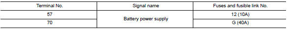
Is the fuse blown?
YES >> Replace the blown fuse or fusible link after repairing the affected circuit.
NO >> GO TO 2.
2.CHECK POWER SUPPLY CIRCUIT
- Disconnect BCM connector M99.
- Check voltage between BCM connector M99 and ground.

Is the inspection result normal?
YES >> GO TO 3.
NO >> Repair harness or connector.
3.CHECK GROUND CIRCUIT
Check continuity between BCM connector M99 and ground.
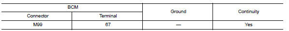
Is the inspection result normal?
YES >> Inspection End.
NO >> Repair harness or connector
Without intelligent key
WITHOUT INTELLIGENT KEY : Diagnosis Procedure
Regarding Wiring Diagram information, refer to BCS "Wiring Diagram".
1.CHECK FUSES AND FUSIBLE LINK
Check that the following fuses and fusible link are not blown.

Is the fuse blown?
YES >> Replace the blown fuse or fusible link after repairing the affected circuit.
NO >> GO TO 2.
2.CHECK POWER SUPPLY CIRCUIT
- Turn ignition switch OFF.
- Disconnect BCM connectors.
- Check voltage between BCM connector and ground.
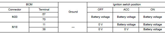
Is the inspection result normal?
YES >> GO TO 3.
NO >> Repair harness or connector.
3.CHECK GROUND CIRCUIT
Check continuity between BCM connector and ground.
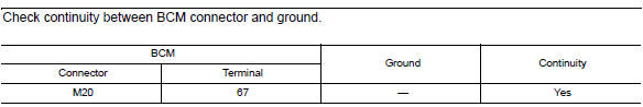
Is the inspection result normal?
YES >> Inspection End.
NO >> Repair harness or connector.
SYMPTOM DIAGNOSIS
TPMS SYMPTOMS
Symptom Table
| Symptom | Reference |
| Low tire pressure warning lamp does not turn ON. |
WT |
| Low tire pressure warning lamp does not turn OFF. | |
| Low tire pressure warning lamp blinks. | |
| ID registration cannot be completed |
 Low tire pressure warning lamp
Component Function Check 1.CHECK THE ILLUMINATION OF THE LOW TIRE PRESSURE WARNING LAMP Check that the low tire pressure warning lamp is turned OFF after illuminating for approximately 1 second, ...
Low tire pressure warning lamp
does not turn on
Diagnosis Procedure NOTE: The Signal Tech II Tool (J-50190) can be used to perform the following functions. Refer to the Signal Tech II User Guide for additional information. Activate and dis ...
Other materials:
RearView Monitor (if so equipped)
1. CAMERA button (models with navigation)
WARNING
Failure to follow the warnings and instructions
for proper use of the Rear-
View Monitor system could result in serious
injury or death.
RearView Monitor is a convenience feature
and is not a substitute for proper
backing. Always ...
Drive belt idler pulley
Exploded View
1. Generator bracket 2. Center shaft 3. Spacer
4. Adjusting bolt 5. Washer 6. Idler pulley
7. Plate
Removal and Installation
REMOVAL
Remove the fender protector (RH).
Remove the air duct inlet assembly.
Remove drive belt.
Remove the lock nut, and then remove the pl ...
Categories
- Manuals Home
- Nissan Versa Owners Manual
- Nissan Versa Service Manual
- Video Guides
- Questions & Answers
- External Resources
- Latest Updates
- Most Popular
- Sitemap
- Search the site
- Privacy Policy
- Contact Us

0.0072