Nissan Versa (N17): RearView Monitor (if so equipped)

1. CAMERA button (models with navigation)
WARNING
- Failure to follow the warnings and instructions for proper use of the Rear- View Monitor system could result in serious injury or death.
- RearView Monitor is a convenience feature and is not a substitute for proper backing. Always turn and look out the windows and check mirrors to be sure that it is safe to move before operating the vehicle. Always back up slowly.
- The system is designed as an aid to the driver in showing large stationary objects directly behind the vehicle, to help avoid damaging the vehicle.
- The distance guide line and the vehicle width line should be used as a reference only when the vehicle is on a level paved surface. The distance viewed on the monitor is for reference only and may be different than the actual distance between the vehicle and displayed objects.
CAUTION
Do not scratch the camera lens when cleaning dirt or snow from the front of the camera.
The RearView Monitor system automatically shows a rear view of the vehicle when the shift lever is shifted into the R (Reverse) position.
Press the CAMERA button (if so equipped) while in the R (Reverse) position to cycle through guideline options. The radio can still be heard while the RearView Monitor is active.
RearView Monitor system operation

To display the rear view, the RearView Monitor system uses a camera located next to the trunk handle 1 .
With the ignition switch in the ON position, move the shift lever to the R (Reverse) position to operate the RearView Monitor.
How to read the displayed lines

Guiding lines which indicate the vehicle width and distances to objects with reference to the vehicle body line A are displayed on the monitor.
Distance guide lines
Indicate distances from the vehicle body.
- Red line 1 : approx. 1.5 ft (0.5 m)
- Yellow line 2 : approx. 3 ft (1 m)
- Green line 3 : approx. 7 ft (2 m)
- Green line 4 : approx. 10 ft (3 m)
Vehicle width guide lines 5
Indicate the vehicle width when backing up.
Difference between predicted and actual distances
The distance guide line and the vehicle width guide line should be used as a reference only when the vehicle is on a level, paved surface. The distance viewed on the monitor is for reference only and may be different than the actual distance between the vehicle and displayed objects.
Backing up on a steep uphill
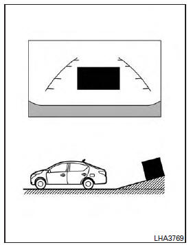
When backing up the vehicle up a hill, the distance guide lines and the vehicle width guide lines are shown closer than the actual distance.
Note that any object on the hill is further than it appears on the monitor.
Backing up on a steep downhill
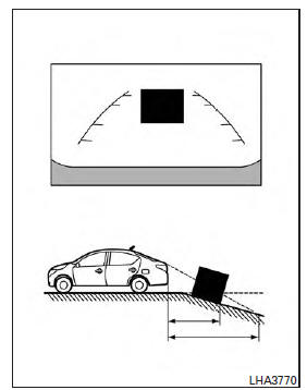
When backing up the vehicle down a hill, the distance guide lines and the vehicle width guide lines are shown farther than the actual distance.
Note that any object on the hill is closer than it appears on the monitor.
Backing up near a projecting object
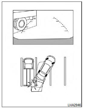
The vehicle may seem to nearly clear the object in the display. However, the vehicle may hit the object if it projects over the actual backing up course.
Backing up behind a projecting object
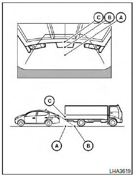
The position C is shown farther than the position B in the display. However, the position C is actually at the same distance as the position A .
The vehicle may hit the object when backing up to the position A if the object projects over the actual backing up course.
Adjusting the screen

Models without navigation
The procedure for adjusting the display settings of the screen differs depending on the type of screen present on the vehicle.
For vehicles without Navigation System
1. Firmly apply the brake and place the shift lever in R (reverse) 2. Press the ENTER/SETTING button.
3. The screen will display the Brightness settings.

Models with navigation
4. Turn the TUNE/SCROLL knob to adjust the setting up or down.
5. Press the ENTER/SETTING button again to display the Contrast settings.
6. Turn the TUNE/SCROLL knob to adjust the setting up or down.
7. Press the ENTER/SETTING button to complete the adjustment.
- Do not adjust the display settings of the RearView Monitor while the vehicle is moving.
For vehicles with Navigation System
1. Firmly apply the brake and place the shift
lever in R (reverse)
2. Press the  button on the control
panel.
button on the control
panel.
3. The screen will display the Night settings.
4. Turn the TUNE knob to adjust the setting up or down.
5. Press the  button again to
access the
Auto settings.
button again to
access the
Auto settings.
6. Turn the TUNE knob to adjust the setting up or down.
- Do not adjust the display settings of the RearView Monitor while the vehicle is moving.
RearView Monitor system limitations
WARNING
Listed below are the system limitations for RearView Monitor. Failure to operate the vehicle in accordance with these system limitations could result in serious injury or death.
- The system cannot completely eliminate blind spots and may not show every object.
- Underneath the bumper and the corner areas of the bumper cannot be viewed on the RearView Monitor because of its monitoring range limitation. The system will not show small objects below the bumper, and may not show objects close to the bumper or on the ground.
- Objects viewed in the RearView Monitor differ from actual distance because a wide-angle lens is used.
- Objects in the RearView Monitor will appear visually opposite compared to when viewed in the rearview and outside mirrors.
- Objects in the RearView Monitor will appear visually opposite compared to when viewed in the rearview and outside mirrors.
- Use the displayed lines as a reference.
The lines are highly affected by the number of occupants, fuel level, vehicle position, road conditions and road grade.
- Make sure that the trunk is securely closed when backing up.
- Do not put anything on the rearview camera. The rearview camera is installed above the license plate.
- When washing the vehicle with high pressure water, be sure not to spray it around the camera. Otherwise, water may enter the camera unit causing water condensation on the lens, a malfunction, fire or an electric shock.
- Do not strike the camera. It is a precision instrument. Otherwise, it may malfunction or cause damage resulting in a fire or an electric shock.
The following are operating limitations and do not represent a system malfunction:
- When the temperature is extremely high or low, the screen may not clearly display objects.
- When strong light directly shines on the camera, objects may not be displayed clearly.
- Vertical lines may be seen in objects on the screen. This is due to strong reflected light from the bumper.
- The screen may flicker under fluorescent light.
- The colors of objects on the RearView Monitor may differ somewhat from the actual color of objects.
- Objects on the monitor may not be clear in a dark environment.
- There may be a delay when switching between views.
- If dirt, rain or snow accumulate on the camera, RearView Monitor may not display objects clearly. Clean the camera.
- Do not use wax on the camera lens. Wipe off any wax with a clean cloth dampened with a diluted mild cleaning agent, then wipe with a dry cloth.
System maintenance

CAUTION
- Do not use alcohol, benzine or thinner to clean the camera. This will cause discoloration.
- Do not damage the camera as the monitor screen may be adversely affected.
If dirt, rain or snow accumulates on the camera 1 , the RearView Monitor may not display objects clearly. Clean the camera by wiping it with a cloth dampened with a diluted mild cleaning agent and then wiping it with a dry cloth.
 Control panel buttons - color screen with Navigation System (if so equipped)
WARNING Positioning of the heating or air conditioning controls and display controls should not be done while driving in order that full attention may be given to the driving operation. ...
Vents
Side vents Adjust the air flow direction of the vents by opening, closing or rotating. Center vents Adjust the air flow direction of the vents by moving the slide as indicated 1 . ...
Other materials:
Evaporative emission system
Inspection
1.CHECK EVAP CANISTER
Block port (B).
Blow air into port (A) and check that it flows freely out of port (C).
Release blocked port (B).
Apply vacuum pressure to port (B) and check that vacuum pressure
exists at the ports (A) and (C).
Block port (A) and (B).
Apply pressure ...
Accelerator control system
Exploded View
1. Accelerator pedal assembly 2. Brake pedal bracket A. Locating hook
B. Locating pin
Removal and Installation
CAUTION:
Do not disassemble accelerator pedal assembly. Do not remove
accelerator pedal position sensor
from accelerator pedal assembly.
Avoid impact from ...
Categories
- Manuals Home
- Nissan Versa Owners Manual
- Nissan Versa Service Manual
- Video Guides
- Questions & Answers
- External Resources
- Latest Updates
- Most Popular
- Sitemap
- Search the site
- Privacy Policy
- Contact Us

0.0122