Nissan Versa (N17): P0138 HO2s2
DTC Logic
DTC DETECTION LOGIC
The heated oxygen sensor 2 has a much longer switching time between rich and lean than the air fuel ratio (A/ F) sensor 1. The oxygen storage capacity of the three way catalyst 1 causes the longer switching time.
MALFUNCTION A
To judge the malfunctions of heated oxygen sensor 2, ECM monitors whether the voltage is unusually high during various driving conditions such as fuel cut.

MALFUNCTION B
To judge the malfunctions of heated oxygen sensor 2, ECM monitors whether the minimum voltage of sensor is sufficiently low during various driving conditions such as fuel cut.

| DTC No. | Trouble diagnosis name | DTC detecting condition | Possible cause | |
| P0138 | Heated oxygen sensor 2 circuit high voltage | A | An excessively high voltage from the sensor is sent to ECM. |
|
| B | The minimum voltage from the sensor is not reached to the specified voltage. |
|
||
DTC CONFIRMATION PROCEDURE
1.PRECONDITIONING OF DTC CONFIRMATION PROCEDURE FOR MALFUNCTION A
If DTC Confirmation Procedure has been previously conducted, always perform the following procedure before conducting the next test.
- Turn ignition switch OFF and wait at least 10 seconds.
- Turn ignition switch ON.
- Turn ignition switch OFF and wait at least 10 seconds.
>> GO TO 2.
2.PERFORM DTC CONFIRMATION PROCEDURE FOR MALFUNCTION A
- Start engine and warm it up to normal operating temperature.
- Turn ignition switch OFF and wait at least 10 seconds.
- Start engine and keep the engine speed between 3,500 and 4,000 rpm for at least 1 minute under no load.
- Let engine idle for 2 minutes.
- Check 1st trip DTC.
Is 1st trip DTC detected?
YES >> Proceed to EC, "Diagnosis Procedure".
NO1 >> With CONSULT: GO TO 3.
NO2 >> Without CONSULT: GO TO 5.
3.PERFORM DTC CONFIRMATION PROCEDURE FOR MALFUNCTION B
NOTE: For better results, perform "DTC WORK SUPPORT" at a temperature of 0 to 30C (32 to 86F).
- Turn ignition switch ON and select "DATA MONITOR" mode of "ENGINE" using CONSULT.
- Start engine and warm it up to normal operating temperature.
- Turn ignition switch OFF and wait at least 10 seconds.
- Start engine and keep the engine speed between 3,500 and 4,000 rpm for at least 1 minute under no load.
- Let engine idle for 1 minute.
- Make sure that "COOLAN TEMP/S" indication is more than 70C (158F).
If not, warm up engine and go to next step when "COOLAN TEMP/S" indication reaches 70C (158F).
- Open engine hood.
- Select "HO2S2 (B1) P1146" of "HO2S2" in "DTC WORK SUPPORT" mode of "ENGINE" using CONSULT.
- Follow the instruction of CONSULT.
NOTE: It will take at most 10 minutes until "COMPLETED" is displayed.
- Touch "SELFDIAG RESULT".
Which is displayed on CONSULT
OK >> INSPECTION END
NG >> Proceed to EC, "Diagnosis Procedure".
CAN NOT BE DIAGNOSED>>GO TO 4.
4.PERFORM DTC CONFIRMATION PROCEDURE FOR MALFUNCTION B AGAIN
- Turn ignition switch OFF and leave the vehicle in a cool place (soak the vehicle).
- Perform DTC confirmation procedure again.
>> GO TO 3.
5.PERFORM COMPONENT FUNCTION CHECK FOR MALFUNCTION B
Perform component function check. Refer to EC, "Component Function Check".
NOTE: Use component function check to check the overall function of the heated oxygen sensor 2 circuit. During this check, a 1st trip DTC might not be confirmed.
Is the inspection result normal?
YES >> INSPECTION END
NO >> Proceed to EC, "Diagnosis Procedure".
Component Function Check
1.PERFORM COMPONENT FUNCTION CHECKI
 Without CONSULT
- Start engine and warm it up to the normal operating temperature.
- Turn ignition switch OFF and wait at least 10 seconds.
- Restart engine and keep the engine speed between 3,500 and 4,000 rpm for at least 1 minute under no load.
- Let engine idle for 1 minute.
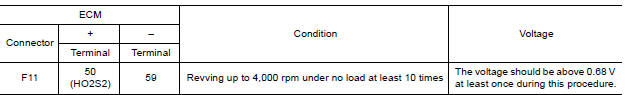
- Check the voltage between ECM harness connector terminals under the following condition.
Is the inspection result normal?
YES >> INSPECTION END
NO >> GO TO 2.
2.PERFORM COMPONENT FUNCTION CHECKII
Check the voltage between ECM harness connector terminals under the following condition.

Is the inspection result normal?
YES >> INSPECTION END
NO >> GO TO 3.
3.PERFORM COMPONENT FUNCTION CHECKIII
Check the voltage between ECM harness connector terminals under the following condition.

Is the inspection result normal?
YES >> INSPECTION END
NO >> Go to EC, "Diagnosis Procedure".
Diagnosis Procedure
1.INSPECTION START
Confirm the detected malfunction (A or B). Refer to EC, "DTC Logic".
Which malfunction is detected?
A >>GO TO 2.
B >>GO TO 9.
2.CHECK GROUND CONNECTION
- Turn ignition switch OFF.
- Check ground connection E15. Refer to Ground Inspection in GI48, "Circuit Inspection".
Is the inspection result normal?
YES >> GO TO 3.
NO >> Repair or replace ground connection.
3.CHECK HO2S2 GROUND CIRCUIT FOR OPEN AND SHORT
- Disconnect heated oxygen sensor 2 harness connector.
- Disconnect ECM harness connector.
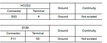
- Check the continuity between HO2S2 harness connector and ECM harness connector.
< DTC/CIRCUIT DIAGNOSIS >

4. Also check harness for short to ground and short to power.
Is the inspection result normal?
YES >> GO TO 4.
NO >> Repair open circuit, short to ground or short to power in harness or connectors.
4.CHECK HO2S2 INPUT SIGNAL CIRCUIT FOR OPEN AND SHORT
1. Check the continuity between HO2S2 harness connector and ECM harness connector.

2. Check the continuity between HO2S2 harness connector and ground or ECM harness connector and ground.
3. Also check harness for short to power.
Is the inspection result normal?
YES >> GO TO 5.
NO >> Repair open circuit, short to ground or short to power in harness or connectors.
5.CHECK HO2S2 CONNECTOR FOR WATER
Check connectors for water.
Is the inspection result normal?
YES >> GO TO 6.
NO >> Repair or replace harness or connectors.
6.CHECK HEATED OXYGEN SENSOR 2
Refer to EC, "Component Inspection".
Is the inspection result normal?
YES >> GO TO 8.
NO >> GO TO 7.
7.REPLACE HEATED OXYGEN SENSOR 2
Replace malfunctioning heated oxygen sensor 2. Refer to EX, "Exploded View".
CAUTION:
- Discard any heated oxygen sensor which has been dropped from a height of more than 0.5 m (19.7 in) onto a hard surface such as a concrete floor; use a new one.
- Before installing new oxygen sensor, clean exhaust system threads using Oxygen Sensor Thread Cleaner [commercial service tool (J4389718 or J4389712)] and approved antiseize lubricant (commercial service tool).
>> INSPECTION END
8.CHECK INTERMITTENT INCIDENT
Refer to GI, "Intermittent Incident".
>> INSPECTION END
9.CHECK GROUND CONNECTION
- Turn ignition switch OFF.
- Check ground connection E15. Refer to Ground Inspection in GI, "Circuit Inspection".
Is the inspection result normal?
YES >> GO TO 10.
NO >> Repair or replace ground connection.
10.CLEAR THE MIXTURE RATIO SELFLEARNING VALUE
- Clear the mixture ratio selflearning value. Refer to EC, "Work Procedure".
- Run engine for at least 10 minutes at idle speed.
Is the 1st trip DTC P0172 detected? Is it difficult to start engine?
YES >> Perform trouble diagnosis for DTC P0172. Refer to EC, "DTC Logic".
NO >> GO TO 11.
11.CHECK HO2S2 GROUND CIRCUIT FOR OPEN AND SHORT
- Turn ignition switch OFF.
- Disconnect heated oxygen sensor 2 harness connector.
- Disconnect ECM harness connector.
- Check the continuity between HO2S2 harness connector and ECM harness connector.

5. Also check harness for short to ground and short to power.
Is the inspection result normal?
YES >> GO TO 12.
NO >> Repair open circuit or short to ground or short to power in harness or connectors.
12.CHECK HO2S2 INPUT SIGNAL CIRCUIT FOR OPEN AND SHORT
1. Check the continuity between HO2S2 harness connector and ECM harness connector.

2. Check the continuity between HO2S2 harness connector or ECM harness connector and ground.

3. Also check harness for short to power.
Is the inspection result normal?
YES >> GO TO 13.
NO >> Repair open circuit, short to ground or short to power in harness or connectors.
13.CHECK HEATED OXYGEN SENSOR 2
Refer to EC, "Component Inspection".
Is the inspection result normal?
YES >> GO TO 15.
NO >> GO TO 14.
14.REPLACE HEATED OXYGEN SENSOR 2
Replace malfunctioning heated oxygen sensor 2. Refer to EX, "Exploded View".
CAUTION:
- Discard any heated oxygen sensor which has been dropped from a height of more than 0.5 m (19.7 in) onto a hard surface such as a concrete floor; use a new one.
- Before installing new oxygen sensor, clean exhaust system threads using Oxygen Sensor Thread Cleaner [commercial service tool (J4389718 or J4389712)] and approved antiseize lubricant (commercial service tool).
>> INSPECTION END
15.CHECK INTERMITTENT INCIDENT
Refer to GI, "Intermittent Incident".
>> INSPECTION END
Component Inspection
1.INSPECTION START
Do you have CONSULT?
YES >> GO TO 2.
NO >> GO TO 3.
2.CHECK HEATED OXYGEN SENSOR 2
 With CONSULT
- Turn ignition switch ON and select "ENGINE" using CONSULT.
- Select "DATA MONITOR" mode.
- Start engine and warm it up to the normal operating temperature.
- Turn ignition switch OFF and wait at least 10 seconds.
- Start engine and keep the engine speed between 3,500 and 4,000 rpm for at least 1 minute under no load.
- Let engine idle for 1 minute.
- Select "FUEL INJECTION" in "ACTIVE TEST" mode, and select "HO2S2 (B1)" as the monitor item with CONSULT.
- Check "HO2S2 (B1)" at idle speed when adjusting "FUEL INJECTION" to +-25%.

"HO2S2 (B1)" should be above 0.68 V at least once when the "FUEL INJECTION" is +25%.
"HO2S2 (B1)" should be below 0.36 V at least once when the "FUEL INJECTION" is −25%.
Is the inspection result normal?
YES >> INSPECTION END
NO >> GO TO 6.
3.CHECK HEATED OXYGEN SENSOR 2I
Without CONSULT
- Start engine and warm it up to the normal operating temperature.
- Turn ignition switch OFF and wait at least 10 seconds.
- Start engine and keep the engine speed between 3,500 and 4,000 rpm for at least 1 minute under no load.
- Let engine idle for 1 minute.
- Check the voltage between ECM harness connector terminals under the following condition.

Is the inspection result normal?
YES >> INSPECTION END
NO >> GO TO 4.
4.CHECK HEATED OXYGEN SENSOR 2II
Check the voltage between ECM harness connector terminals under the following condition.

Is the inspection result normal?
YES >> INSPECTION END
NO >> GO TO 5.
5.CHECK HEATED OXYGEN SENSOR 2III
Check the voltage between ECM harness connector terminals under the following condition.

Is the inspection result normal?
YES >> INSPECTION END
NO >> GO TO 6.
6.REPLACE HEATED OXYGEN SENSOR 2
Replace malfunctioning heated oxygen sensor 2. Refer to EX, "Exploded View".
CAUTION:
- Discard any heated oxygen sensor which has been dropped from a height of more than 0.5 m (19.7 in) onto a hard surface such as a concrete floor; use a new one.
- Before installing new oxygen sensor, clean exhaust system threads using Oxygen Sensor Thread Cleaner [commercial service tool (J4389718 or J4389712)] and approved antiseize lubricant (commercial service tool).
>> INSPECTION END
 P0137 HO2s2
Other materials:
Ignition coil, spark plug and rocker cover
Exploded View
1. Ignition coil 2. Spark plug 3. Rocker cover
4. Hose cramp 5. PCV hose 6. PCV valve
7. Oring 8. Gasket 9. Oil filler cap
10. Oring 11. Intake camshaft position sensor 12. Exhaust camshaft position
sensor
13. Clip A. To intake manifold
Removal and Installation
REMOVAL
...
Service data and specifications
(SDS)
Idle Speed
*: Under the following conditions
A/C switch: OFF
Electric load: OFF (Lights, heater fan & rear window defogger)
Steering wheel: Kept in straight-ahead position
Ignition Timing
*: Under the following conditions
A/C switch: OFF
Ele ...
Categories
- Manuals Home
- Nissan Versa Owners Manual
- Nissan Versa Service Manual
- Video Guides
- Questions & Answers
- External Resources
- Latest Updates
- Most Popular
- Sitemap
- Search the site
- Privacy Policy
- Contact Us

0.0073