Nissan Versa (N17): Generator
Exploded View

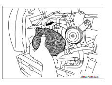
1. Generator bracket bolt 2. Generator bracket 3. Generator bolt 4. Generator 5. "B" terminal harness 6. "B" terminal nut 7. Generator harness connector
Removal and Installation
REMOVAL
1. Disconnect the battery cable from the negative terminal. Refer to PG "Removal and Installation".
2. Remove fender protector (RH). Refer to EXT "Removal and Installation".
3. Remove the under cover. Refer to EXT "Removal and Installation".
4. Remove drive belt. Refer to EM "Removal and Installation".
5. Remove the horn bracket.
6. Disconnect the harness connector from the generator.
7. Remove "B" terminal nut and disconnect "B" terminal harness.
8. Remove generator bolts.
9. Remove the generator.
CAUTION: Be careful not to damage surrounding parts when removing generator from the vehicle.
NOTE: Front fascia shown removed for clarity.
10. Remove generator bracket if necessary.
INSTALLATION
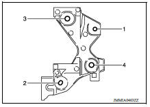
1. Install the generator bracket (if removed), using the following procedure.
a. Temporarily tighten bolt (1).
b. Temporarily tighten bolt (2).
c. Tighten bolts (3) and (4) to specification in numerical order as shown.
Tighten bolts (1) and (2) to specification.
2. Install generator using the following procedure.
a. Temporarily tighten the generator bolts in order from the lower to the upper.
b. Tighten the generator bolts to the specification starting with the top bolt.
c. Install "B" terminal harness and "B" terminal nut.
CAUTION: Be sure to tighten "B" terminal nut carefully.
3. Install and check the tension of the drive belt. Refer to EM "Removal and Installation".
4. Installation of the remaining components is in the reverse order of removal.
SERVICE DATA AND SPECIFICATIONS (SDS)
Generator
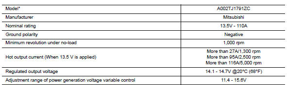
* : Always check with the Parts Department for the latest parts information.
 S Terminal circuit
Description The output voltage of the generator is controlled by the IC regulator at terminal "S" detecting the input voltage from battery. The "S" terminal circuit detects the battery voltage ...
Precautions
Precaution for Supplemental Restraint System (SRS) "AIR BAG" and "SEAT BELT PRE-TENSIONER" The Supplemental Restraint System such as "AIR BAG" and "SEAT BELT PRE-TENSIONER", us ...
Other materials:
Head restraints/headrests
WARNING
Head restraints/headrests supplement
the other vehicle safety systems. They may
provide additional protection against injury
in certain rear end collisions. Adjustable
head restraints/headrests must be
adjusted properly, as specified in this section.
Check the adjustment after someo ...
Seat belt retractor
SEAT BELT RETRACTOR : Removal and Installation
REMOVAL
CAUTION:
Before servicing, turn ignition switch OFF, disconnect battery negative terminal
and wait at least three
minutes.
Disconnect both the negative and positive battery cables, then wait at
least three minutes. Refer to PG " ...
Categories
- Manuals Home
- Nissan Versa Owners Manual
- Nissan Versa Service Manual
- Video Guides
- Questions & Answers
- External Resources
- Latest Updates
- Most Popular
- Sitemap
- Search the site
- Privacy Policy
- Contact Us

0.0052