Nissan Versa (N17): Engine coolant
Inspection
CHECKING COOLING SYSTEM HOSES
Check hoses for the following:
- Improper attachment
- Leaks
- Cracks
- Damage
- Loose connections
- Chafing
- Deterioration
CHECKING RESERVOIR LEVEL
- Check that the reservoir tank engine coolant level is within the MAX (A) to MIN (B) range when the engine is cool.
- Adjust the engine coolant level if necessary.
CAUTION:
Refill the engine cooling system with the specified coolant or equivalent.

CHECKING COOLING SYSTEM FOR LEAKS
To check for leaks, apply pressure to the cooling system using suitable tool (A) and Tool (B).
Tool number (B) : EG17650301 (J33984A)
WARNING:
Do not remove the radiator cap when the engine is hot. Serious burns could occur from highpressure coolant escaping from the radiator.
CAUTION:
Higher test pressure than specified may cause radiator damage.

Draining Engine Coolant
WARNING:
- Do not remove radiator cap when engine is hot. Serious burns could occur from highpressure engine coolant escaping from radiator.
- Wrap a thick cloth around the radiator cap. Slowly turn it a
quarter of a turn to release builtup pressure.
Then turn it all the way.
- Remove engine under cover.
- Connect a drain hose to the radiator drain plug.
- Use a suitable hose with the dimensions as shown.
Diameter (A) : 0.8 mm (0.31 in)
Length (B) : 300 mm (11.81 in)

3. Open radiator drain plug (A) at the bottom of radiator, and then remove radiator cap.
 : Front
CAUTION:
- Perform this step when engine is cold.
- Do not spill engine coolant on the drive belt.

- It is necessary to drain the cylinder block when draining all of engine coolant in the system. To drain the cylinder block, open the water drain plugs on cylinder block.
- Remove reservoir tank if necessary, and drain engine coolant and clean reservoir tank before installing.
- Check drained engine coolant for contaminants such as rust, corrosion or discoloration. If contaminated, flush the engine cooling system.
Refilling Engine Coolant
1. Install the radiator drain plug. Install the reservoir tank and cylinder block drain plug, if removed.
CAUTION:
- Be sure to clean drain plug and install with a new Oring.
- Apply sealant to the threads of the cylinder block drain plug. Use Genuine High Performance Thread Sealant or equivalent.
2. Set the vehicle heater controls to the full HOT and heater ON position. Turn the vehicle ignition ON with the engine OFF as necessary to activate the heater mode.
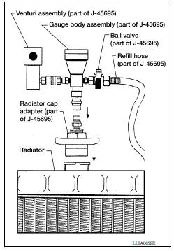
3. Install the Tool by installing the radiator cap adapter onto the radiator neck opening. Then attach the gauge body assembly with the refill tube and the venturi assembly to the radiator cap adapter.
Tool number : KV991J0070 (J45695)
4. Insert the refill hose into the coolant mixture container that is placed at floor level. Make sure the ball valve is in the closed position
CAUTION:
Do not use any cooling system additives such as radiator sealer. Additives may clog the cooling system and cause damage to the engine, transmission and/or cooling system.
NOTE:
Use recommended coolant or equivalent.
5. Install an air hose to the venturi assembly. The air pressure must be within specification.
Compressed airsupply pressure: 549 824 kPa (5.6 8.4 kg/cm2,80 119 psi)
CAUTION:
The compressed air supply must be equipped with an air dryer.
6. The vacuum gauge will begin to rise and there will be an audible hissing noise. During this process open the ball valve on the refill hose slightly. Coolant will be visible rising in the refill hose. Once the refill hose is full of coolant, close the ball valve. This will purge any air trapped in the refill hose.
7. Continue to draw the vacuum until the gauge reaches 28 inches of vacuum. The gauge may not reach 28 inches in high altitude locations; use the vacuum specifications based on the altitude above sea level.
Altitude above sea level Vacuum gauge reading0 100 m (328 ft) : 28 inches of vacuum
300 m (984 ft) : 27 inches of vacuum
500 m (1,641 ft) : 26 inches of vacuum
1,000 m (3,281 ft) : 24 25 inches of vacuum

8. When the vacuum gauge has reached the specified amount, disconnect the air hose and wait 20 seconds to see if the system loses any vacuum. If the vacuum level drops, perform any necessary repairs to the system and repeat steps 6 8 to bring the vacuum to the specified amount. Recheck for any leaks.
9. Place the coolant container (with the refill hose inserted) at the same level as the top of the radiator. Then open the ball valve on the refill hose so the coolant will be drawn up to fill the cooling system. The cooling system is full when the vacuum gauge reads zero.
CAUTION:
Do not allow the coolant container to get too low when filling, to avoid air from being drawn into the cooling system.
10. Remove the Tool from the radiator neck opening.
11. Fill the cooling system reservoir tank to the specified level and install the radiator cap. Run the engine to warm up the cooling system and top up the system as necessary.
12. Install engine under cover.
Flushing Cooling System
1. Install radiator drain plug and reservoir tank, if removed.
CAUTION:
Be sure to clean drain plug and install with new Oring.
2. If water drain plugs on cylinder block were removed, close and tighten them.
3. Remove air duct from between air cleaner case and electric throttle control actuator.
4. Disconnect heater hose (1) at location ( ) as shown.
 Front
Front
- Position heater hose as high as possible.

- Fill radiator until engine coolant flows out of the disconnected heater hose and then reconnect the heater hose.
- Finish filling the engine and reservoir tank with water and reinstall the radiator cap.
- Install air duct in between air cleaner case and electric throttle control actuator.
- Run the engine and warm it up to normal operating temperature.
- Rev the engine two or three times under noload.
- Stop the engine and wait until it cools down.
- Drain water from the system.
- Repeat steps 1 through 11 until clear water begins to drain from radiator.
 Description
Engine Cooling System M/T models CVT and A/T models Engine Cooling System Schematic M/T models CVT and A/T models OVERHEATING CAUSE ANALYSIS Troubleshooting Chart ...

Other materials:
Instrument panel
1. Headlight/turn signal switch/fog light
switch (if so equipped)
2. Driver's supplemental air bag (P. 1-39)
Horn
3. Meters and gauges. Warning and indicator lights
4. Wiper and washer switch
5. Vents
6. Rear window defroster switch
7. Front passenger air bag status light
8. Hazard warn ...
Trunk lid
WARNING
Do not drive with the trunk lid open. This
could allow dangerous exhaust gases
to be drawn into the vehicle. For additional
information, refer to "Exhaust
gas (carbon monoxide)" in the "Starting
and driving" section of this manual.
Closely supervise children when they
are a ...
Categories
- Manuals Home
- Nissan Versa Owners Manual
- Nissan Versa Service Manual
- Video Guides
- Questions & Answers
- External Resources
- Latest Updates
- Most Popular
- Sitemap
- Search the site
- Privacy Policy
- Contact Us

0.0077