Nissan Versa (N17): U1244 GPS Antenna
DTC Logic
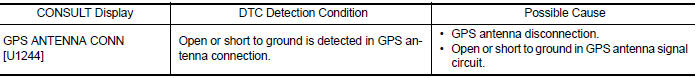
DTC DETECTION LOGIC
Diagnosis Procedure
Regarding Wiring Diagram information, refer to AV "Wiring Diagram".
1.GPS ANTENNA INSPECTION
Visually inspect the GPS antenna and antenna feeder. Refer to AV "Removal and Installation".
Is inspection result normal?
YES >> GO TO 2.
NO >> Repair or replace malfunctioning components.
2.CHECK AV CONTROL UNIT VOLTAGE
1. Disconnect AV control unit connector M91.
2. Turn ignition switch ON.
3. Check voltage between AV control unit connector M91 and ground.
Is inspection result normal?
YES >> Replace GPS antenna. Refer to AV "Removal and Installation".
NO >> Replace AV control unit. Refer to AV "Removal and Installation".
 U1000 CAN Comm circuit
DTC Logic DTC DETECTION LOGIC Diagnosis Procedure 1.PERFORM SELF DIAGNOSTIC RESULT 1. Turn ignition switch ON and wait for 2 seconds or more. 2. Perform Self Diagnostic Result for MULTI AV. Is C ...
U1258 Satellite radio antenna
DTC Logic DTC DETECTION LOGIC Diagnosis Procedure Regarding Wiring Diagram information, refer to AV "Wiring Diagram". 1.SATELLITE ANTENNA INSPECTION Visually inspect ...
Other materials:
Engine protection control at low engine oil pressure
Engine protection control at low engine oil pressure : system diagram
Engine protection control at low engine
oil pressure : system description
INPUT/OUTPUT SIGNAL CHART
Sensor
Input signal to ECM
ECM function
Actuator
Engine oil pressure sensor
Engine pressure
...
Fuel pressure check
Work Procedure
FUEL PRESSURE RELEASE
1.FUEL PRESSURE RELEASE
With CONSULT
Turn ignition switch ON.
Perform "FUEL PRESSURE RELEASE" in "WORK SUPPORT" mode with CONSULT.
Start engine.
After engine stalls, crank it two or three times to release all fuel
pressure.
Turn ignition switc ...
Categories
- Manuals Home
- Nissan Versa Owners Manual
- Nissan Versa Service Manual
- Video Guides
- Questions & Answers
- External Resources
- Latest Updates
- Most Popular
- Sitemap
- Search the site
- Privacy Policy
- Contact Us

0.0104