Nissan Versa (N17): TCM
Reference Value
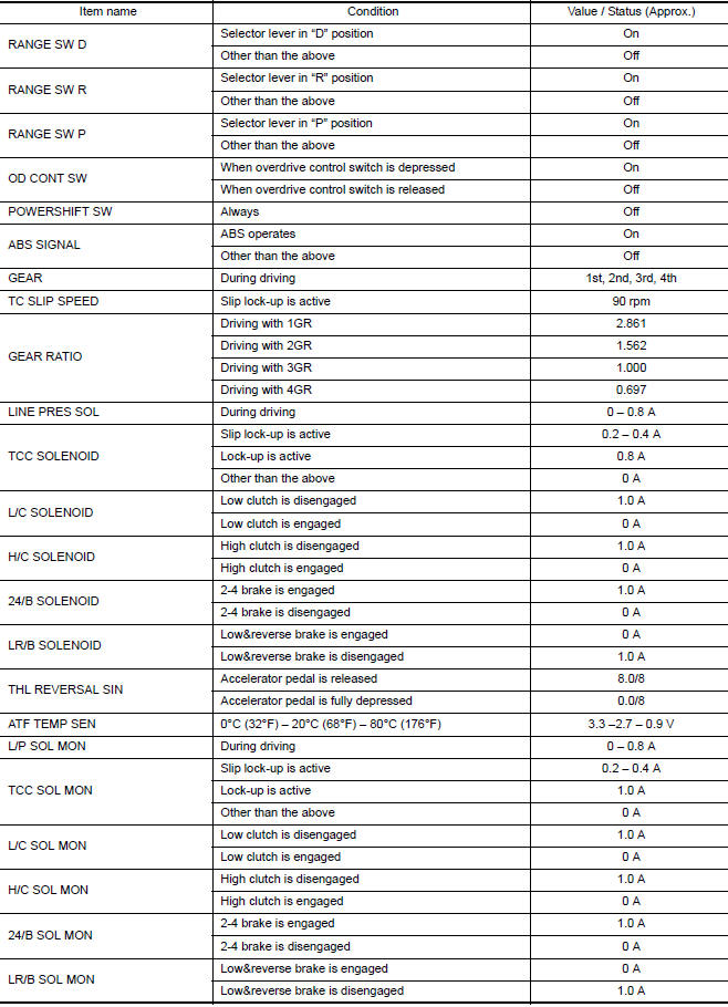
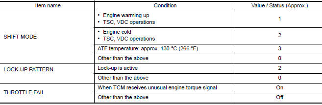
VALUES ON DIAGNOSIS TOOL
- The CONSULT electrically displays shift timing and lock-up timing (that is, operation timing of each solenoid) Check for time difference between actual shift timing and the CONSULT display. If the difference is noticeable, mechanical parts (except solenoids, sensors, etc.) may be malfunctioning. Check mechanical parts in accordance with the specified diagnostic procedures.
- Shift schedule (that implies gear position) on CONSULT may slightly differ from that described in Service Manual. This occurs for the following reasons:
- Actual shift schedule has more or less tolerance or allowance
- Shift schedule in Service Manual refers to the point where shifting starts
- Gear position on CONSULT indicates the point where shifting completes
- Display of solenoid valves on CONSULT changes at the start of shifting, while gear position is displayed upon completion of shifting (which is computed by TCM).
NOTE: The following table includes information (items) inapplicable to this vehicle. For information (items) applicable to this vehicle, refer to CONSULT display items.


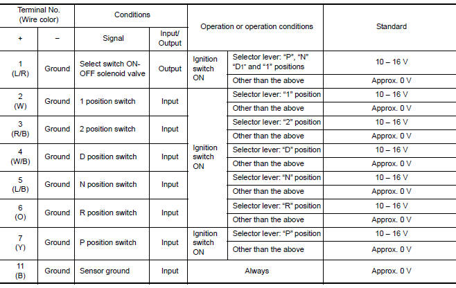
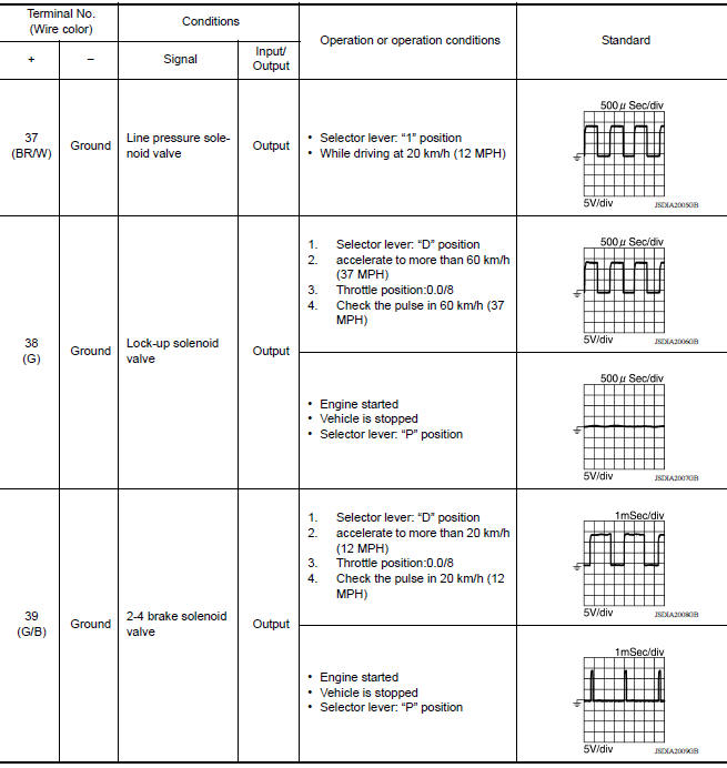
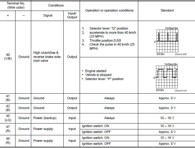
TERMINAL LAYOUT

INPUT/OUTPUT SIGNAL STANDARD

Fail-Safe
TCM is equipped with an electrical fail-safe mode. The operation can be continued even if the signal circuit of the main electronically controlled input/output parts are damaged.
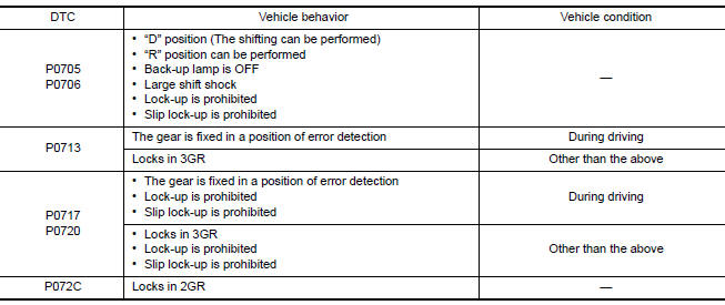
If the vehicle shows following behaviors including "poor acceleration", a malfunction of the applicable system is detected by TCM and the vehicle may be in a fail-safe mode. At this time, check the DTC code and perform inspection and repair according to the malfunction diagnosis procedures.
FAIL-SAFE FUNCTION

Protection Control
The TCM becomes the protection control status temporarily to protect the safety when the safety of TCM and transmission is lost. It automatically returns to the normal status if the safety is secured.
The TCM is equipped with the following protection control.
REVERSE INHIBIT CONTROL
Intercepts the torque transmission and shifts to the neutral status if the selector lever is shifted to "R" position while the vehicle moves forward at the vehicle speed 10 km/h (7 MPH) or more.
| Operation detection conditions |
|
| Control when activated | Neutral |
| Recovery condition |
|
| Vehicle behavior |
|
TCM HIGH TEMPERATURE PROTECTION CONTROL
When the ATF becomes hot, the shifting pattern is changed for preventing fluid temperature rise.
| Operation detection conditions | ATF temp.: 125C (257F) or more |
| Control when activated | Change the shift pattern so that higher upshift may be achieved. |
| Recovery condition |
|
| Vehicle behavior | Upshifts at a higher vehicle speed than usual. |
TORQUE-DOWN CONTROL WHEN CONTINUOUS STALL OCCURS IN D POSITION
If the accelerator pedal is continually depressed for a certain length of time when the selector lever is in the "D" position and the vehicle is parked, the engine output is limited for protecting the transaxle
| Operation detection conditions | The following conditions continue for 20 seconds or more
|
| Control when activated | Limits engine output |
| Recovery condition |
|
| Vehicle behavior |
|
O/D PROHIBIT CONTROL AT LOW TEMPERATURES
When the ATF temperature is low immediately after engine start, shifting to 4GR is prohibited for protecting the transaxle and allowing the exhaust gas characteristics to warm up quickly.
| Operation detection conditions |
|
| Control when activated | 4GR prohibited |
| Recovery condition | Less than 130 seconds following IGN ON
|
| Vehicle behavior | Shifts up only as far as 3GR. |
DTC Inspection Priority Chart
If some DTCs are displayed at the same time, perform inspections one by one based on the priority as per the following list.


DTC Index
NOTE:
- If some DTCs are displayed at the same time, perform inspections one by one based on the priority as per the following list. Refer to TM, "DTC Inspection Priority Chart".
- The IGN counter is indicated in Freeze frame data (FFD). Refer to TM, "CONSULT Function".
×: Applicable -: Not Applicable


*1: These numbers are prescribed by SAE J2012/ISO 15031-6.
*2: The items are the same as those of 1st trip freeze frame data.
A/T CONTROL SYSTEM
Wiring Diagram


A/T SHIFT LOCK SYSTEM
Wiring Diagram


 Consult function
APPLICATION ITEMS Diagnostic test mode Function Work Support This mode enables a technician to adjust some devices faster and more accurately. Self Diagnostic Resul ...

Other materials:
Automatic speed control device (ASCD)
Automatic speed control device (ascd) : system diagram
NOTE:
Transmission range switch and TCM is also for A/T models.
Automatic speed control device (ascd) : system description
INPUT/OUTPUT SIGNAL CHART
Sensor
Input signal to ECM
ECM function
Actuator
Brake pedal ...
U0101 can comm circuit
Description
CAN (Controller Area Network) is a serial communication line for real time
application. It is an onvehicle multiplex
communication line with high data communication speed and excellent error
detection ability. Many electronic
control units are equipped onto a vehicle, and each con ...
Categories
- Manuals Home
- Nissan Versa Owners Manual
- Nissan Versa Service Manual
- Video Guides
- Questions & Answers
- External Resources
- Latest Updates
- Most Popular
- Sitemap
- Search the site
- Privacy Policy
- Contact Us

0.0096