Nissan Versa (N17): System
Relay control system
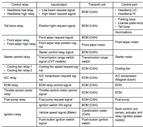
RELAY CONTROL SYSTEM : System Diagram
SYSTEM DIAGRAM

RELAY CONTROL SYSTEM : System Description
DESCRIPTION
IPDM E/R activates the internal control circuit to perform the relay ON-OFF control according to the input signals from various sensors and the request signals received from control units via CAN communication.
CAUTION: IPDM E/R integrated relays cannot be removed.
Power consumption control system
POWER CONSUMPTION CONTROL SYSTEM : System Diagram

POWER CONSUMPTION CONTROL SYSTEM : System Description
DESCRIPTION
Outline
- IPDM E/R incorporates a power consumption control function that reduces the power consumption according to the vehicle status.
- IPDM E/R changes its status (control mode) with the sleep wake up signal received from BCM via CAN communication.
Normal mode (wake-up)
- CAN communication is normally performed with other control units.
- Individual unit control by IPDM E/R is normally performed.
Low power consumption mode (sleep)
- Low power consumption control is active.
- CAN transmission is stopped.
Sleep Mode Activation
- IPDM E/R judges that the sleep-ready conditions are fulfilled when the ignition switch is OFF and none of the conditions below are present. Then it transmits a sleep-ready signal (ready) to BCM via CAN communication.
- Outputting signals to actuators
- Switches or relays operating
- Output requests are being received from control units via CAN communication.
- IPDM E/R stops CAN communication and enters the low power consumption mode when it receives a sleep wake up signal (sleep) from BCM and the sleep-ready conditions are fulfilled.
Wake-up Operation
- IPDM E/R changes from the low power consumption mode to the normal mode when it receives a sleep wake-up signal (wake up) from BCM or any of the following conditions is fulfilled. In addition, it transmits a sleep-ready signal (not-ready) to BCM via CAN communication to report the CAN communication start.
- Ignition switch ON
- An output request is received from a control unit via CAN communication.
 Precautions
Precaution for Supplemental Restraint System (SRS) "AIR BAG" and "SEAT BELT PRE-TENSIONER" The Supplemental Restraint System such as "AIR BAG" and "SEAT BELT PRE-TENSIONER", us ...
Diagnosis system (IPDM E/R)
Diagnosis Description AUTO ACTIVE TEST Description In auto active test, the IPDM E/R sends a drive signal to the following systems to check their operation. Front wiper (LO, HI) Parking l ...
Other materials:
Jump starting
To start your engine with a booster battery, the
instructions and precautions below must be followed.
WARNING
If done incorrectly, jump starting can
lead to a battery explosion, resulting in
severe injury or death. It could also
damage your vehicle.
Explosive hydrogen gas is always pre ...
Structure and operation
TRANSAXLE
TRANSAXLE : Cross-Sectional View
1. Converter housing 2. Oil pump 3. Counter drive gear
4. Control valve 5. Oil pan 6. Primary pulley
7. Steel belt 8. Secondary pulley 9. Planetary gear (auxiliary gearbox)
10. Side cover 11. Transaxle case 12. Differential case
13. Final gear ...
Categories
- Manuals Home
- Nissan Versa Owners Manual
- Nissan Versa Service Manual
- Video Guides
- Questions & Answers
- External Resources
- Latest Updates
- Most Popular
- Sitemap
- Search the site
- Privacy Policy
- Contact Us

0.0077