Nissan Versa (N17): Refrigerant
Description
CONNECTION OF SERVICE TOOLS AND EQUIPMENT
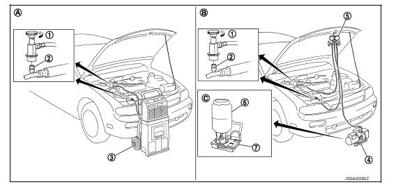
1. Shut-off valve 2. A/C service valve 3. Recovery/recycling/recharging equipment 4. Vacuum pump 5. Manifold gauge set 6. Refrigerant container (HFC-134a) 7. Weight scale A. Preferred (best) method B. Alternative method C. For charging
Leak Test
CHECK REFRIGERANT LEAKAGE USING FLUORESCENT LEAK DETECTION DYE
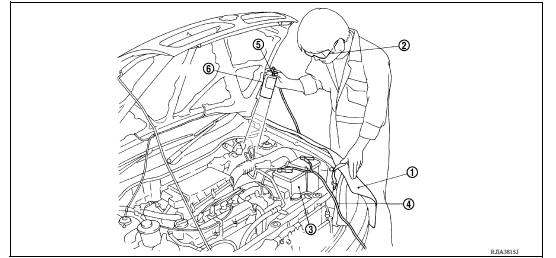
- Install a fender cover (1).
- Wear UV safety goggles (2) provided with refrigerant dye leak detection kit.
- Connect power cable (4) of UV lamp (6) to positive and negative terminals of the battery (3).
- Turn on UV lamp switch (5) and check A/C system for refrigerant leakage. (Where refrigerant leakage occurs, fluorescent leak detection dye appears in green color.)
WARNING: Do not look directly into UV lamp light source.
NOTE:
- For continuous operating time of UV lamp, follow the manufacturer operating instructions.
- Illuminate piping joints from different angles using UV lamp and check that there is no leakage.
- Use a mirror in areas that are difficult to see to check for refrigerant leakage.
- Refrigerant leakage from evaporator can be detected by soaking cotton swab or a similar material with drain hose water and illuminating it using UV lamp.
- Dust, dirt, and packing materials adhesive used for condenser, evaporator, and other components may cause fluoresce. Be careful not to misidentify leakage.
- Repair or replace parts where refrigerant leakage occurs and wipe off
fluorescent leak detection dye.
NOTE: Completely wipe off fluorescent leak detection dye from gaps between parts, screw threads, and other items using a cotton swab or similar materials.
- Use a UV lamp to check that no fluorescent leak detection dye remains
after finishing work.
WARNING: Do not look directly into UV lamp light source.
NOTE:
- For continuous operating time of UV lamp, follow the manufacturer operating instructions.
- Dust, dirt, and packing materials adhesive used for condenser, evaporator, and other items may cause fluoresce. Be careful not to misidentify leakage.
CHECK REFRIGERANT LEAKAGE USING ELECTRICAL LEAK DETECTOR
WARNING: Do not check for refrigerant leakage while the engine is running.
CAUTION: Be careful of the following items so that inaccurate checks or misidentifications are avoided.
- Do not allow refrigerant vapor, shop chemical vapors, cigarette smoke, etc. around the vehicle.
- Always check refrigerant leakage in a low air flow environment so that refrigerant may not disperse when leakage occurs.
- Stop the engine.
- Connect recovery/recycling/recharging equipment or manifold gauge set to A/C service valve.
- Check that A/C refrigerant pressure is 345 kPa (3.52 kg/cm2, 50 psi) or
more when temperature is 16C
(61F) or more. When pressure is lower than the specified value, recycle
refrigerant completely and fill
refrigerant to the specified level.
NOTE: Leakages may not be detected if A/C refrigerant pressure is 345 kPa (3.52 kg/cm2, 50 psi) or less when temperature is less than 16C (61F).
- Clean area where refrigerant leakage check is performed, and check refrigerant leakage along all surfaces of pipe connections and A/C system components using electrical leak detector probe.
CAUTION:
- Continue checking when a leak is found. Always continue and complete checking along all pipe connections and A/C system components for additional leakage.
- When a leak is detected, clean leakage area using compressed air and check again.
- When checking leakage of cooling unit inside, always clean inside of drain hose so that the probe surface is not exposed to water or dirt.
NOTE:
- Always check leakage starting from high-pressure side and continue to low-pressure side.
- When checking leakage of cooling unit inside, operate blower fan motor for 15 minutes or more at the maximum fan speed while the engine is stopped, and then insert electrical leak detector probe into drain hose and hold for 10 minutes or more.
- When disconnecting shut-off valve that is connected to A/C service valve, always evacuate remaining refrigerant so that misidentification can be avoided.
- Repair or replace parts where refrigerant leakage is detected. (Leakage is detected but leakage area is unknown. GO TO 6.)
- Start the engine and set A/C control in the following positions.
- A/C switch ON
- Air flow: VENT (ventilation)
- Intake door position: Recirculation
- Temperature setting: Full cold
- Fan speed: Maximum speed set
- Run the engine at approximately 1,500 rpm for 2 minutes or more.
- Stop the engine. Check again for refrigerant leakage. GO TO 4.
WARNING: Be careful not to get burned when the engine is hot.
NOTE:
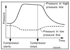
- Start refrigerant leak check immediately after the engine is stopped.
- When refrigerant circulation is stopped, pressure on the lowpressure side rises gradually, and after this, pressure on the high-pressure side falls gradually.
- The higher the pressure is, the easier it is to find the refrigerant leakage.
Recycle Refrigerant
WARNING:
- Always use HFC-134a for A/C refrigerant. If CFC-12 is accidentally charged, compressor will be damaged due to insufficient lubrication.
- Always observe and follow precautions described on refrigerant container. Incorrect handling may result in an explosion of refrigerant container, frostbite, or the loss of eyesight.
- Do not breathe A/C refrigerant and oil vapor or mist. Exposure may irritate eyes, nose, or throat.
- Do not allow HFC-134a to be exposed to an open flame etc. because it generates poisonous gas when in contact with high temperature objects. Keep workshop well ventilated.
- Perform oil return operation. Refer to HA "Perform Oil Return Operation". (If refrigerant or oil leakage is detected in a large amount, omit this step, and then GO TO 2.) CAUTION: Do not perform oil return operation if a large amount of refrigerant or oil leakage is detected.
- Check gauge pressure readings of recovery/recycling/recharging
equipment. When remaining pressure
exists, recycle refrigerant from high-pressure hose and low-pressure hose.
NOTE: Follow manufacturer instructions for the handling or maintenance of the equipment. Do not fill the equipment with non-specified refrigerant.
- Remove A/C service valve cap from the vehicle.
- Connect recovery/recycling/recharging equipment to A/C service valve.
- Operate recovery/recycling/recharging equipment, and recycle refrigerant from the vehicle.
- Evacuate air for 10 minutes or more to remove any remaining refrigerant mixed with compressor oil, etc.
- Refrigerant recycle operation is complete.
Charge Refrigerant
WARNING:
- Always use HFC-134a for A/C refrigerant. If CFC-12 is accidentally charged, compressor will be damaged due to insufficient lubrication.
- Always observe and follow precautions described on refrigerant container. Incorrect handling may result in an explosion of refrigerant container, frostbite, or the loss of eyesight.
- Do not breathe A/C refrigerant and oil vapor or mist. Exposure may irritate eyes, nose, or throat.
- Do not allow HFC-134a to be exposed to an open flame etc. because it generates poisonous gas when in contact with high-temperature objects. Keep workshop well ventilated.
- Connect recovery/recycling/recharging equipment to the A/C service valve.
- Operate recovery/recycling/recharging equipment, and evacuate air from
A/C system for 25 minutes or
more.
CAUTION: Evacuate air for 15 minutes or more if the parts are replaced.
- Check the airtightness of A/C system for 25 minutes or more. If pressure
rises more than the specified
level, charge A/C system with approximately 200 g (0.4 lb) refrigerant and
check that there is no refrigerant
leakage. Refer to HA "Leak Test".
CAUTION: Check the airtightness for 15 minutes or more if the parts are replaced.
- If parts other than compressor are replaced, fill compressor oil according to parts that are replaced.
- Charge the specified amount of refrigerant to A/C system.
- Check that A/C system operates normally.
- Disconnect recovery/recycling/recharging equipment. (Collect the refrigerant from the high-pressure hose and low-pressure hose of recovery/recycling/recharging equipment.)
- Install A/C service valve cap.
- Refrigerant charge is complete.
 Diagnosis and repair workflow
Workflow OVERALL SEQUENCE DETAILED FLOW 1.INTERVIEW CUSTOMER Interview the customer to obtain as much information as possible about the conditions and environment under which the malfunctio ...
Oil
Description MAINTENANCE OF OIL LEVEL The compressor oil is circulating in the system together with the refrigerant. It is necessary to fill compressor with oil when replacing A/C system parts or ...
Other materials:
U0101 can comm circuit
Description
CAN (Controller Area Network) is a serial communication line for real time
application. It is an onvehicle multiplex
communication line with high data communication speed and excellent error
detection ability. Many electronic
control units are equipped onto a vehicle, and each con ...
P0506 ISC system
Description
The ECM controls the engine idle speed to a specified level through the fine
adjustment of the air, which is let
into the intake manifold, by operating the electric throttle control actuator.
The operating of the throttle valve is
varied to allow for optimum control of the engine ...
Categories
- Manuals Home
- Nissan Versa Owners Manual
- Nissan Versa Service Manual
- Video Guides
- Questions & Answers
- External Resources
- Latest Updates
- Most Popular
- Sitemap
- Search the site
- Privacy Policy
- Contact Us

0.0098