Nissan Versa (N17): Push-button ignition switch illumination circuit
Description
Provides the power supply and the ground to control the push-button ignition switch illumination.
Component Function Check
1.CHECK PUSH-BUTTON IGNITION SWITCH ILLUMINATION OPERATION
CONSULT
1. Turn the ignition switch ON.
2. Select ENGINE SW ILLUMI of BCM (INTELLGENT KEY) active test item.
3. While operating the test item, check that the push-button ignition switch illumination turns ON/OFF
ON : Push-button ignition switch illumination ON
OFF : Push-button ignition switch illumination OFF
Is the inspection result normal?
YES >> Push-button ignition switch illumination circuit is normal.
NO >> Refer to INL "Diagnosis Procedure".
Diagnosis Procedure
Regarding Wiring Diagram information, refer to INL "Wiring Diagram".
1.CHECK PUSH-BUTTON IGNITION SWITCH ILLUMINATION OPERATION
CONSULT
1. Turn the ignition switch ON.
2. Select ENGINE SW ILLUMI of BCM (INTELLIGENT KEY) active test item.
3. While operating the test item, check voltage between push-button ignition
switch connector M25 terminal
5 and ground.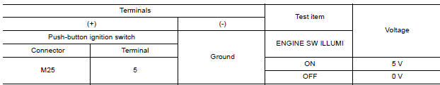
Is the inspection result normal?
YES >> GO TO 4
NO >> GO TO 2
2.CHECK PUSH-BUTTON IGNITION SWITCH ILLUMINATION POWER SUPPLY OPEN CIRCUIT
1. Turn the ignition switch OFF.
2. Disconnect BCM connector M98 and push-button ignition switch connector.
3. Check continuity between BCM connector M98 terminal 90 and push-button
ignition switch connector
M25 terminal 5.
Is the inspection result normal?
YES >> GO TO 3.
NO >> Repair or replace the harness or connectors.
3.CHECK PUSH-BUTTON IGNITION SWITCH ILLUMINATION POWER SUPPLY SHORT CIRCUIT
Check continuity between BCM connector M98 terminal 90 and ground.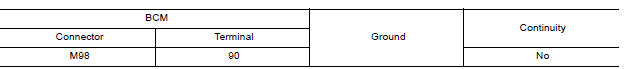
Is the inspection result normal?
YES >> Replace BCM. Refer to BCS "Removal and Installation".
NO >> Repair or replace the harness or connectors.
4.CHECK PUSH-BUTTON IGNITION SWITCH ILLUMINATION GROUND CIRCUIT
1. Turn the ignition switch OFF
2. Disconnect push-button ignition switch connector.
3. Check continuity between push-button ignition switch connector M25
terminal 6 and ground.
Is the inspection result normal?
YES >> Replace push-button ignition switch. Refer to PCS "Removal and Installation".
NO >> GO TO 5.
5.CHECK PUSH-BUTTON IGNITION SWITCH ILLUMINATION GROUND OPEN CIRCUIT
1. Disconnect BCM connector M98.
2. Check continuity between BCM connector M98 terminal 92 and push-button
ignition switch connector
M25 terminal 6.
Is the inspection result normal?
YES >> Replace BCM. Refer to BCS "Removal and Installation".
NO >> Repair or replace the harness or connectors.
SYMPTOM DIAGNOSIS
INTERIOR LIGHTING SYSTEM SYMPTOMS
Symptom Table
CAUTION: Perform the self-diagnosis with CONSULT before the symptom diagnosis. Perform the trouble diagnosis if any DTC is detected.

REMOVAL AND INSTALLATION
 Trunk room lamp circuit
Description Controls the trunk room lamp (ground side) to turn the trunk room lamp ON and OFF. Component Function Check CAUTION: Before performing the diagnosis, check that the following is ...
Map lamp
Exploded View 1. Map lamp bulb housing 2. Bulb 3. Lens Pawl ...
Other materials:
Towing your vehicle
When towing your vehicle, all State (Provincial in
Canada) and local regulations for towing must be
followed. Incorrect towing equipment could damage
your vehicle. Towing instructions are available
from a NISSAN dealer. Local service operators
are generally familiar with the applicable laws
an ...
Stall test
Work Procedure
INSPECTION
Check the engine oil level. Replenish if necessary.
Check for leak of the CVT fluid. Refer to TM "Inspection".
Drive for about 10 minutes to warm up the vehicle so that the CVT fluid
temperature is 50 to 80C (122 to
176F).
Be sure to apply the par ...
Categories
- Manuals Home
- Nissan Versa Owners Manual
- Nissan Versa Service Manual
- Video Guides
- Questions & Answers
- External Resources
- Latest Updates
- Most Popular
- Sitemap
- Search the site
- Privacy Policy
- Contact Us

0.0077