Nissan Versa (N17): Precautions
Precaution for Supplemental Restraint System (SRS) "AIR BAG" and "SEAT BELT PRETENSIONER"
The Supplemental Restraint System such as "AIR BAG" and "SEAT BELT PRETENSIONER", used along with a front seat belt, helps to reduce the risk or severity of injury to the driver and front passenger for certain types of collision. This system includes seat belt switch inputs and dual stage front air bag modules. The SRS system uses the seat belt switches to determine the front air bag deployment, and may only deploy one front air bag, depending on the severity of a collision and whether the front occupants are belted or unbelted.
Information necessary to service the system safely is included in the SR and SB section of this Service Manual.
WARNING:
- To avoid rendering the SRS inoperative, which could increase the risk of personal injury or death in the event of a collision which would result in air bag inflation, all maintenance must be performed by an authorized NISSAN/INFINITI dealer.
- Improper maintenance, including incorrect removal and installation of the SRS, can lead to personal injury caused by unintentional activation of the system. For removal of Spiral Cable and Air Bag Module, see the SR section.
- Do not use electrical test equipment on any circuit related to the SRS unless instructed to in this Service Manual. SRS wiring harnesses can be identified by yellow and/or orange harnesses or harness connectors.
PRECAUTIONS WHEN USING POWER TOOLS (AIR OR ELECTRIC) AND HAMMERS
WARNING:
- When working near the Airbag Diagnosis Sensor Unit or other Airbag System sensors with the Ignition ON or engine running, DO NOT use air or electric power tools or strike near the sensor(s) with a hammer. Heavy vibration could activate the sensor(s) and deploy the air bag(s), possibly causing serious injury.
- When using air or electric power tools or hammers, always switch the Ignition OFF, disconnect the battery, and wait at least 3 minutes before performing any service.
Precaution for Procedure without Cowl Top Cover
When performing the procedure after removing cowl top cover, cover the lower end of windshield with urethane, etc.

Draining Engine Coolant
Drain engine coolant and engine oil when the engine is cooled.
Disconnecting Fuel Piping
- Before starting work, check no fire or spark producing items are in the work area.
- Release fuel pressure before disconnecting and disassembly.
- After disconnecting pipes, plug openings to stop fuel leakage.
Removal and Disassembly
- When instructed to use SST, use specified tools. Always be careful to work safely, avoid forceful or uninstructed operations.
- Use care to avoid damage to mating or sliding surfaces.
- Dowel pins are used for several parts alignment. When replacing and reassembling parts with dowel pins, check that dowel pins are installed in the original position.
- Cover openings of engine system with a tape or equivalent, if necessary, to seal out foreign materials.
- Mark and arrange disassembly parts in an organized way for easy troubleshooting and reassembly.
- When loosening nuts and bolts, start with the one furthest outside, then the one diagonally opposite, and so on. If the order of loosening is specified, do exactly as specified. Power tools may be used in the step.
Inspection, Repair and Replacement
Before repairing or replacing, thoroughly inspect parts. Inspect new replacement parts in the same way, and replace if necessary.
Assembly and Installation
- Use torque wrench to tighten bolts or nuts to specification.
- Tighten nuts and bolts in order exactly as specified in the procedure. If a tightening order or procedure is not specified, tighten nuts and bolts equally in several different steps. Start with the nuts or bolts in the center and then tighten diagonally starting with the inside and moving to the outside in a spiral pattern.
- Replace with new gasket, packing, oil seal or Oring.
- Thoroughly wash, clean, and airblow each part. Carefully check engine oil or engine coolant passages for restrictions and blockages.
- Avoid damaging sliding or mating surfaces. Before assembling, completely remove foreign materials such as cloth lint or dust, and oil the sliding surfaces.
- After refilling engine coolant, bleed the air from the cooling system.
- After repairing, start the engine and increase engine speed to check for engine coolant leaks, fuel leaks, engine oil leaks, and exhaust gas leaks.
Parts Requiring Angle Tightening
- For the final tightening of the following engine parts use Tool:
Tool number : KV10112100 (BT8653A)
- Camshaft sprocket (INT) bolt
- Cylinder head bolts
- Main bearing cap bolts
- Connecting rod cap bolts
- Crankshaft pulley bolt (Note an angle wrench is required as bolt flange is provided with notches for angle tightening)
- Do not use a torque value for final tightening.
- The torque value for these parts are for a preliminary step.
- Ensure thread and seat surfaces are clean and coated with engine oil.
Precaution for Liquid Gasket
REMOVAL OF LIQUID GASKET SEALANT
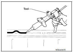
- After removing the bolts and nuts, separate the mating surface and remove the old liquid gasket sealant using Tool.
Tool number : KV10111100 (J37228)
CAUTION:
Do not damage mating surfaces.
- Tap the seal cutter to insert it (1).
- In areas where the Tool is difficult to use, lightly tap to slide it (2).

LIQUID GASKET APPLICATION PROCEDURE
- Remove the old liquid gasket adhering to the gasket application surface and the mating surface using suitable tool.
- Remove the liquid gasket completely from the groove of the liquid gasket application surface, bolts, and bolt holes.
- Thoroughly clean the mating surfaces and remove adhering moisture, grease and foreign material.

- Attach the liquid gasket tube to the suitable tool. Use Genuine RTV Silicone Sealant or equivalent.
- Apply the liquid gasket without breaks to the specified location with the specified dimensions.
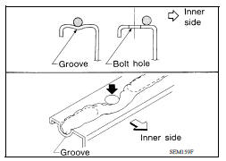
- If there is a groove for the liquid gasket application, apply the liquid gasket to the groove.
- Normally apply the liquid gasket on the inside edge of the bolt holes. Also apply to the outside edge of the bolt holes when specified in the procedure.
- Within five minutes of liquid gasket application, install the mating component.
- If the liquid gasket protrudes, wipe it off immediately.
- Do not retighten after the installation.
- Wait 30 minutes or more after installation before refilling the engine with oil or coolant.
CAUTION:
Carefully follow all of the warnings, cautions, notes, and procedures contained in this manual.
 Accelerator control system (ACC)
Preparation
Special Service Tools The actual shapes of KentMoore tools may differ from those of special service tools illustrated here. Tool number (KentMoore No.) Tool name Description ...
Other materials:
EVAP canister
Exploded View
1. EVAP control system pressure sensor 2. O-ring 3. EVAP canister
4. Hose clamp 5. EVAP canister purge hose 6. EVAP vent line
7. O-ring 8. EVAP canister vent control valve 9. EVAP canister vent control
valve
hose
A. Mount to vehicle bracket
Removal and Installation
NOTE: ...
P0974 Shift solenoid A
DTC Logic
DTC DETECTION LOGIC
DTC
Trouble diagnosis name
DTC detection condition
Possible causes
P0974
Shift Solenoid "A" Control Circuit
High
The following diagnosis conditions
are met, and the TCM select
switch ON-OFF solenoid
valve monitor value is OF ...
Categories
- Manuals Home
- Nissan Versa Owners Manual
- Nissan Versa Service Manual
- Video Guides
- Questions & Answers
- External Resources
- Latest Updates
- Most Popular
- Sitemap
- Search the site
- Privacy Policy
- Contact Us

0.0086