Nissan Versa (N17): Power supply and ground circuit
Audio unit
AUDIO UNIT : Diagnosis Procedure
Regarding Wiring Diagram information, refer to AV"Wiring Diagram".
1.CHECK FUSE
Check that the following fuses are not blown.
Are the fuses blown?
YES >> Replace the blown fuse after repairing the affected circuit.
NO >> GO TO 2.
2.CHECK POWER SUPPLY CIRCUIT
1. Turn ignition switch OFF.
2. Disconnect audio unit connector M44.
3. Check voltage between audio unit connector M44 and ground.
Is the inspection result normal?
YES >> GO TO 3.
NO >> Repair or replace harness or connectors.
3.CHECK GROUND CIRCUIT
1. Turn ignition switch OFF.
2. Disconnect audio unit connector M45.
3. Check continuity between audio unit connector M45 and ground.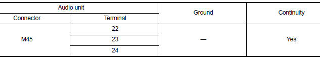
Is the inspection result normal?
YES >> Inspection End.
NO >> Repair or replace harness or connectors.
Bluetooth control unit
BLUETOOTH CONTROL UNIT : Diagnosis Procedure
Regarding Wiring Diagram information, refer to AV "Wiring Diagram".
1.CHECK FUSE
Check that the following fuses are not blown.
Are the fuses blown?
YES >> Replace the blown fuse after repairing the affected circuit.
NO >> GO TO 2.
2.CHECK POWER SUPPLY CIRCUIT
1. Turn ignition switch OFF.
2. Disconnect Bluetooth control unit connector B33.
3. Check voltage between Bluetooth control unit connector B33 and ground.
Is the inspection result normal?
YES >> GO TO 3.
NO >> Repair or replace harness or connectors.
3.CHECK GROUND CIRCUIT
1. Turn ignition switch OFF.
2. Check continuity between Bluetooth control unit connector B33 and ground.
Is the inspection result normal?
YES >> Inspection End.
NO >> Repair or replace harness or connectors.
 Diagnosis and repair workflow
Work Flow OVERALL SEQUENCE DETAILED FLOW 1.GET INFORMATION FOR SYMPTOM Get detailed information from the customer about the symptom (the condition and the environment when the incident/malf ...
Front door speaker
Diagnosis Procedure Regarding Wiring Diagram information, refer to AV "Wiring Diagram". 1.CONNECTOR CHECK Check the audio unit and speaker connectors for the following: Proper conne ...
Other materials:
P0973 Shift solenoid A
DTC Logic
DTC DETECTION LOGIC
DTC
Trouble diagnosis name
DTC detection condition
Possible causes
P0973
Shift Solenoid "A" Control Circuit
Low
The following diagnosis conditions
are met, and the TCM select
switch ON-OFF solenoid
valve monitor value is ON c ...
Shift lock system
SHIFT LOCK SYSTEM : Component Parts Location
1. Stop lamp switch 2. Shift lock release lever 3. Park position switch
4. Shift lock solenoid
Component
Function
Stop lamp switch
Stop lamp switch turns ON when brake pedal is depressed
Shift lock release lever
Ma ...
Categories
- Manuals Home
- Nissan Versa Owners Manual
- Nissan Versa Service Manual
- Video Guides
- Questions & Answers
- External Resources
- Latest Updates
- Most Popular
- Sitemap
- Search the site
- Privacy Policy
- Contact Us

0.0109