Nissan Versa (N17): Power supply and ground circuit
Combination meter
COMBINATION METER : Diagnosis Procedure
Regarding Wiring Diagram information, refer to MWI"Wiring Diagram".
1.CHECK FUSE
Check for blown combination meter fuses.
Is the inspection result normal?
YES >> GO TO 2.
NO >> Replace the fuse after repairing the affected circuit.
2.CHECK POWER SUPPLY CIRCUIT
Check voltage between combination meter harness connector and ground.
1. Turn ignition switch to OFF.
2. Disconnect combination meter connector.
3. Check voltage between combination meter harness connector M24 terminals 1,
3 and ground.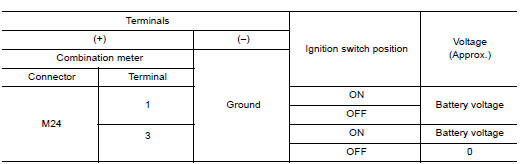
Is the inspection result normal?
YES >> GO TO 3.
NO >> Check harness between combination meter and fuse.
3.CHECK GROUND CIRCUIT
1. Turn ignition switch OFF.
2. Check continuity between combination meter harness connector M24 terminals
21, 22, 23 and ground.
Is the inspection result normal?
YES >> INSPECTION END
NO >> Repair harness or connector.
BCM (Body control module)
BCM (BODY CONTROL MODULE) : Diagnosis Procedure
Regarding Wiring Diagram information, refer to BCS "Wiring Diagram".
1.CHECK FUSES AND FUSIBLE LINK
Check that the following fuses and fusible link are not blown. 
Is the fuse blown?
YES >> Replace the blown fuse or fusible link after repairing the affected circuit.
NO >> GO TO 2.
2.CHECK POWER SUPPLY CIRCUIT
1. Turn ignition switch OFF.
2. Disconnect BCM connectors.
3. Check voltage between BCM connector and ground.
Is the inspection result normal?
YES >> GO TO 3.
NO >> Repair harness or connector.
3.CHECK GROUND CIRCUIT
Check continuity between BCM connector and ground. 
Is the inspection result normal?
YES >> Inspection End.
NO >> Repair harness or connector.
 B2267 Engine speed
Description The engine speed signal is transmitted from ECM to the combination meter via CAN communication. DTC Logic DTC DETECTION LOGIC Diagnosis P ...
Fuel level sensor signal circuit
Description The fuel level sensor unit and fuel pump detects the approximate fuel level in the fuel tank and transmits the fuel level signal to the combination meter. ...
Other materials:
Automatic speed control device (ASCD)
Automatic speed control device (ascd)
: switch name and function
SWITCHES AND INDICATORS
1. CRUISE indicator 2. CANCEL switch 3. ACCEL/RES switch
4. COAST/SET switch 5. ASCD MAIN switch
A. On the combination meter B. On the steering wheel
SET SPEED RANGE
ASCD system can be set the follow ...
P0711 Transmission fluid temperature
sensor A
DTC Logic
DTC DETECTION LOGIC
DTC
Trouble diagnosis name
DTC detection condition
Possible causes
P0711
Transmission Fluid Temperature
Sensor A Circuit Range/
Performance
Under the following diagnosis conditions, CVT
fluid temperature does not rise to 10C (5 ...
Categories
- Manuals Home
- Nissan Versa Owners Manual
- Nissan Versa Service Manual
- Video Guides
- Questions & Answers
- External Resources
- Latest Updates
- Most Popular
- Sitemap
- Search the site
- Privacy Policy
- Contact Us

0.0078