Nissan Versa (N17): Power supply and ground circuit
Diagnosis Procedure
Regarding Wiring Diagram information, refer to BCS "Wiring Diagram".
1.CHECK FUSES AND FUSIBLE LINK
Check that the following fuses and fusible link are not blown. 
Is the fuse blown?
YES >> Replace the blown fuse or fusible link after repairing the affected circuit.
NO >> GO TO 2.
2.CHECK POWER SUPPLY CIRCUIT
1. Turn ignition switch OFF.
2. Disconnect BCM connectors.
3. Check voltage between BCM connector and ground.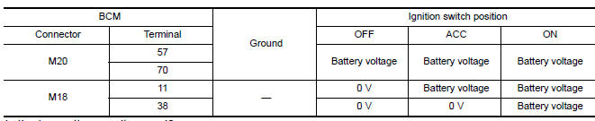
Is the inspection result normal?
YES >> GO TO 3.
NO >> Repair harness or connector.
3.CHECK GROUND CIRCUIT
Check continuity between BCM connector and ground. 
Is the inspection result normal?
YES >> Inspection End.
NO >> Repair harness or connector.
 B2196 Dongle unit
Description BCM performs ID verification between BCM and dongle unit. When verification result is OK, BCM permits cranking. ...
Vehicle security indicator
Description Vehicle security indicator is built in combination meter. NATS (Nissan Anti-Theft System) condition is indicated by blink or illumination of vehicle security indicator. ...
Other materials:
Precautions
Precaution for Supplemental Restraint System
(SRS) "AIR BAG" and "SEAT BELT PRE-TENSIONER"
The Supplemental Restraint System such as "AIR BAG" and "SEAT BELT PRE-TENSIONER",
used along
with a front seat belt, helps to reduce the risk or severity of injury to the
driver and ...
Clutch pedal
Exploded View
1. Clutch pedal 2. Pedal stopper rubber 3. Pedal pad
4. Clip 5. Clutch interlock switch
Removal and Installation
REMOVAL
Remove the instrument lower panel LH. Refer to IP, "Removal and
Installation".
Disconnect master cylinder rod end from clutch pedal.
D ...
Categories
- Manuals Home
- Nissan Versa Owners Manual
- Nissan Versa Service Manual
- Video Guides
- Questions & Answers
- External Resources
- Latest Updates
- Most Popular
- Sitemap
- Search the site
- Privacy Policy
- Contact Us

0.0068