Nissan Versa (N17): P2101 electric throttle control function
DTC Logic
DTC DETECTION LOGIC
NOTE:
- If DTC P2101 is displayed with DTC P2100, first perform the trouble diagnosis for DTC P2100. Refer to EC, "DTC Logic".
- If DTC P2101 is displayed with DTC P2119, first perform the trouble diagnosis for DTC P2119. Refer to EC, "DTC Logic".
| DTC No. | Trouble diagnosis name | DTC detecting condition | Possible cause |
| P2101 | Electric throttle control performance | Electric throttle control function does not operate properly. |
|
DTC CONFIRMATION PROCEDURE
1.PRECONDITIONING
If DTC Confirmation Procedure has been previously conducted, always perform the following before conducting the next test.
- Turn ignition switch OFF and wait at least 10 seconds.
- Turn ignition switch ON.
- Turn ignition switch OFF and wait at least 10 seconds.
TESTING CONDITION: Before performing the following procedure, confirm that battery voltage is more than 11 V when engine is running.
>> GO TO 2.
2.PERFORM DTC CONFIRMATION PROCEDURE
- Turn ignition switch ON and wait at least 2 seconds.
- Start engine and let it idle for 5 seconds.
- Check DTC.
Is DTC detected?
YES >> Go to EC, "Diagnosis Procedure".
NO >> INSPECTION END
Diagnosis Procedure
1.CHECK GROUND CONNECTION
- Turn ignition switch OFF.
- Check ground connection E15. Refer to Ground Inspection in GI, "Circuit Inspection".
Is the inspection result normal?
YES >> GO TO 2.
NO >> Repair or replace ground connection.
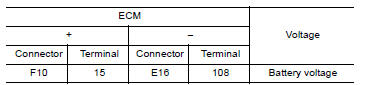
2.CHECK THROTTLE CONTROL MOTOR RELAY INPUT SIGNAL CIRCUIT
- Turn ignition switch ON.
- Check the voltage between ECM harness connector and ground.

Is the inspection result normal?
YES >> GO TO 11.
NO >> GO TO 3.
3.CHECK THROTTLE CONTROL MOTOR RELAY POWER SUPPLY CIRCUIT-I
- Turn ignition switch OFF.
- Check voltage between ECM harness connector and ground.
Is the inspection result normal?
YES >> GO TO 7.
NO >> GO TO 4.
4.CHECK THROTTLE CONTROL MOTOR RELAY POWER SUPPLY CIRCUIT-II
- Disconnect ECM harness connector.
- Disconnect IPDM E/R harness connector F42.
- Check the continuity between ECM harness connector and IPDM E/R harness
connector.
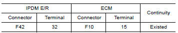
- Also check harness for short to ground and short to power.
Is the inspection result normal?
YES >> GO TO 6.
NO >> GO TO 5.
5.DETECT MALFUNCTIONING PART
Check the following.
- IPDM E/R connector F42
- Harness for open or short between IPDM E/R and ECM
>> Repair open circuit or short to ground or short to power in harness or connectors.
6.CHECK FUSE
- Disconnect 20 A fuse (No. 53) from IPDM E/R.
- Check 20 A fuse for blown.
Is the inspection result normal?
YES >> GO TO 10.
NO >> Replace 20 A fuse.
7.CHECK THROTTLE CONTROL MOTOR RELAY POWER SUPPLY CIRCUIT-III
- Disconnect ECM harness connector.
- Disconnect IPDM E/R harness connector F42.
- Check the continuity between ECM harness connector and IPDM E/R harness
connector.
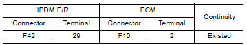
- Also check harness for short to ground and short to power.
Is the inspection result normal?
YES >> GO TO 10.
NO >> GO TO 8.
8.DETECT MALFUNCTIONING PART
Check the following.
- IPDM E/R connector F42
- Harness for open or short between IPDM E/R and ECM
>> Repair open circuit or short to ground or short to power in harness or connectors.
9.CHECK FUSE
- Disconnect 15 A fuse (No. 52) from IPDM E/R.
- Check 15 A fuse for blown.
Is the inspection result normal?
YES >> GO TO 10.
NO >> Replace 15 A fuse.
10.CHECK INTERMITTENT INCIDENT
Refer to GI, "Intermittent Incident".
Is the inspection result normal?
YES >> Replace IPDM E/R. Refer to PCS, "Removal and Installation" (WITH I-KEY) or PCS, "Removal and Installation" (WITHOUT I-KEY).
NO >> Repair or replace harness or connectors.
11.CHECK THROTTLE CONTROL MOTOR OUTPUT SIGNAL CIRCUIT FOR OPEN OR SHORT
- Turn ignition switch OFF.
- Disconnect electric throttle control actuator harness connector.
- Disconnect ECM harness connector.
- Check the continuity between electric throttle control actuator harness
connector and ECM harness connector.
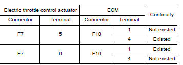
- Also check harness for short to ground and short to power.
Is the inspection result normal?
YES >> GO TO 12.
NO >> Repair or replace harness or connectors.
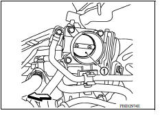
12.CHECK ELECTRIC THROTTLE CONTROL ACTUATOR VISUALLY
- Remove the intake air duct. Refer to EM, "Removal and Installation"
- Check if foreign matter is caught between the throttle valve (1) and the housing.
Vehicle front
Is the inspection result normal?
YES >> GO TO 13.
NO >> Remove the foreign matter and clean the electric throttle control actuator inside, and then perform throttle valve closed position learning. Refer to EC, "Work Procedure".
13.CHECK THROTTLE CONTROL MOTOR
Refer to EC, "Component Inspection".
Is the inspection result normal?
YES >> GO TO 14.
NO >> GO TO 15.
14.CHECK INTERMITTENT INCIDENT
Refer to GI, "Intermittent Incident".
Is the inspection result normal?
YES >> GO TO 15.
NO >> Repair or replace harness or connectors.
15.REPLACE ELECTRIC THROTTLE CONTROL ACTUATOR
Replace malfunction electric throttle control actuator. Refer to EM, "Removal and Installation".
>> INSPECTION END
Component Inspection
1.CHECK THROTTLE CONTROL MOTOR
- Disconnect electric throttle control actuator harness connector.
- Check resistance between electric throttle control actuator terminals as
follows.

Is the inspection result normal?
YES >> INSPECTION END
NO >> GO TO 2.
2.REPLACE ELECTRIC THROTTLE CONTROL ACTUATOR
Replace electric throttle control actuator. Refer to EM, "Removal and Installation".
>> INSPECTION END
 P2100, P2103 throttle control motor
relay
P2100, P2103 throttle control motor
relay
Other materials:
P1212 TCS communication line
Description
This CAN communication line is used to control the smooth engine operation
during the TCS operation. Pulse
signals are exchanged between ECM and "ABS actuator and electric unit (control
unit)".
Be sure to erase the malfunction information such as DTC not only for "ABS
actuat ...
Trunk lid finisher
Exploded View
1. Trunk lid finisher 2. Emblem 3. Rear view camera (if equipped)
Pawl Clip
Removal and Installation
REMOVAL
1. Remove trunk lid finisher inner. Refer to INT "Removal and Installation".
2. Remove trunk lid finisher nuts.
3. Disconnect the harness connectors from ...
Categories
- Manuals Home
- Nissan Versa Owners Manual
- Nissan Versa Service Manual
- Video Guides
- Questions & Answers
- External Resources
- Latest Updates
- Most Popular
- Sitemap
- Search the site
- Privacy Policy
- Contact Us

0.0086