Nissan Versa (N17): P117A air fuel ratio
DTC Logic
DTC DETECTION LOGIC
NOTE: If DTC P117A is displayed with other DTC, first perform the trouble diagnosis for the other DTC. Refer to EC, "DTC Index".
| DTC No. | CONSULT screen terms (Trouble diagnosis content) | DTC detecting condition | Possible cause |
| P117A | AIR FUEL RATIO B1 (AIR FUEL RATIO B1) | ECM detects a lean/rich air fuel ratio state in any cylinder for a specified length of time. |
|
DTC CONFIRMATION PROCEDURE
1.PRECONDITIONING-1
If DTC Confirmation Procedure has been previously conducted, always perform the following before conducting the next test.
- Turn ignition switch OFF and wait at least 10 seconds.
- Turn ignition switch ON.
- Turn ignition switch OFF and wait at least 10 seconds.
NOTE: Before performing the following procedure, confirm that battery voltage is 11 V or more at idle.
>> GO TO 2.
- 2.PRECONDITIONING-2
- Turn ignition switch ON.
- Clear the mixture ratio self-learning value. Refer to EC, "Work Procedure".
Will CONSULT be used?
YES >> GO TO 3.
NO >> GO TO 6.
3.PERFORM DTC CONFIRMATION PROCEDURE-1
- Turn ignition switch ON.
- Select "COOLAN TEMP/S" in "DATA MONITOR" mode of "ENGINE" using CONSULT.
- Start engine.
- Make sure that "COOLAN TEMP/S" indicates more than 80C (176F).
>> GO TO 4.
4.PERFORM DTC CONFIRMATION PROCEDURE-2
With CONSULT
- Select "SYSTEM 1 DIAGNOSIS B B1" and "SYSTEM 1 DIAGNOSIS A B1" in "DATA MONITOR" mode of "ENGINE" using CONSULT.
- Drive vehicle under the following conditions for at least 5 consecutive seconds.
CAUTION: Always drive vehicle at a safe speed.

NOTE:
- Drive the vehicle at approximately 88 km/h (55MPH) allows easy diagnosis.
- Keep the accelerator pedal as possible during crusing.
3. Check "SYSTEM 1 DIAGNOSIS A B1" indication.
Is "CMPLT" displayed?
YES >> GO TO 5.
NO >> GO TO 2.
5.PERFORM DTC CONFIRMATION PROCEDURE-3
Check 1st trip DTC.
Is 1st trip DTC detected?
YES >> Proceed to EC, "Diagnosis Procedure".
NO >> INSPECTION END
6.PERFORM DTC CONFIRMATION PROCEDURE-4
Without CONSULT
- Start the engine and warm it up to normal operating temperature.
- Drive vehicle under the following conditions for at least 5 consecutive seconds.
CAUTION: Always drive vehicle at a safe speed.

NOTE:
- Drive the vehicle at approximately 88 km/h (55MPH) allows easy diagnosis.
- Keep the accelerator pedal as possible during crusing.
3. Check 1st trip DTC.
Is 1st trip DTC detected?
YES >> Proceed to EC, "Diagnosis Procedure".
NO >> INSPECTION END
Diagnosis Procedure
1.CHECK FOR INTAKE AIR LEAK
1. Stop engine and check the following for connection.
- Air duct
- Vacuum hoses
- PCV hose
- Intake air passage between air duct to intake manifold
2. Start engine and let it idle.
3. Listen for an intake air leak after the mass air flow sensor.
Is the inspection result normal?
YES >> GO TO 2.
NO >> Repair or replace error-detected parts.
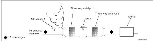
2.CHECK EXHAUST GAS LEAK
- Stop engine and visually check exhaust tube, three way catalyst and muffler for dents connection.
- Start engine and let it idle.
- Listen for an exhaust gas leak before three way catalyst (manifold).
Is the inspection result normal?
YES >> GO TO 3.
NO >> Repair or replace error-detected parts.
3.CHECK FUEL PRESSURE
- Release fuel pressure to zero. Refer to EC, "Work Procedure".
- Check fuel pressure. Refer to EC, "Work Procedure".
Is the inspection result normal?
YES >> GO TO 4.
NO >> GO TO 9.
4.CHECK MASS AIR FLOW SENSOR
With CONSULT
Check "MASS AIRFLOW" in "DATA MONITOR" mode of "ENGINE" using CONSULT.
For specification, refer to EC, "Mass Air Flow Sensor".
With GST
Check mass air flow sensor signal in Service $01 using GST.
For specification, refer to EC, "Mass Air Flow Sensor".
Is the inspection result normal?
YES >> GO TO 5.
NO >> Check connectors for rusted terminals or loose connections in the mass air flow sensor circuit or grounds. Refer to EC, "Diagnosis Procedure".
5.CHECK FUNCTION OF FUEL INJECTOR-1
With CONSULT
- Start engine.
- Perform "POWER BALANCE" in "ACTIVE TEST" mode of "ENGINE" using CONSULT.
- Check that each circuit produces a momentary engine speed drop.
Without CONSULT
- Let engine idle.
- Listen to each fuel injector operating sound.
Clicking noise should be heard.
Is the inspection result normal?
YES >> GO TO 6.
NO >> Perform trouble diagnosis for fuel injector, refer to EC, "Component Function Check".
6.CHECK FUNCTION OF FUEL INJECTOR-2
CAUTION: Perform the following procedure in a place with no combustible objects and good ventilation.
- Turn ignition switch OFF.
- Confirm that the engine is cooled down and there are no fire hazards near the vehicle.
- Disconnect all fuel injector harness connectors.
- Remove fuel tube assembly. Refer to EM, "Removal and Installation".
Keep fuel hose and all fuel injectors connected to fuel tube.
- Disconnect all ignition coil harness connectors.
- Prepare pans or saucers under each fuel injector.
- Crank engine for approximately 3 seconds.
- Fuel should be sprayed evenly for each fuel injector.
- Fuel must not drip from the tip of fuel injector.
Is the inspection result normal?
YES >> GO TO 7.
NO >> Replace fuel injector. Refer to EM, "Removal and Installation".

7.CHECK FUNCTION OF IGNITION COIL-1
CAUTION: Perform the following steps in a well-ventilated area with no combustibles.
- Turn ignition switch OFF.
- Remove fuel pump fuse from IPDM E/R to release fuel pressure.
NOTE: CONSULT must not be used to release fuel pressure. It develops again during the following steps, if released by using CONSULT.
- Start the engine.
- After an engine stall, crank the engine two or three times to release all the fuel pressure.
- Turn ignition switch OFF.
- Disconnect all the harness connectors of ignition coil to prevent electric discharge from occurring in ignition coil.
- Remove ignition coil assembly and spark plug of cylinder. Refer to EM, "Removal and Installation".
- Crank engine for 5 seconds or more to remove combustion gas in the cylinder.
- Connect spark plug and harness connector to ignition coil.
- Allow a 13-17mm (0.52-0.66 in) spacing between spark plug and grounded metal portion as shown in the figure to fix the ignition coil with a rope or an equivalent.
- Crank the engine for approximately 3 seconds to see if sparking occurs between spark plug and the grounded metal portion.
Spark should be generated.

CAUTION:
- The discharge voltage becomes 20 kV or higher. Therefore, always stay away from the spark plug and ignition coil at least 50 cm (19.7 in) during the inspection.
- Leaving a space of more than 17mm (0.66 in) may damage the ignition coil.
NOTE: When the gap is less than 13 mm (0.52 in), a the spark might be generated even if the coil is malfunctioning.
Is the inspection result normal?
YES >> GO TO 8.
NO >> GO TO 10.
8.CHECK COMPRESSION PRESSURE
Check compression pressure. Refer to EM, "Inspection".
Is the inspection result normal?
YES >> Check intermittent incident. Refer to GI, "Intermittent Incident".
NO >> Check pistons, piston rings, valves, valve seats and cylinder head gaskets.
9.DETECT MALFUNCTIONING PART
Check fuel hoses and fuel tubes for clogging.
Is the inspection result normal?
YES >> Replace fuel filter and fuel pump assembly. Refer to FL, "Exploded View".
NO >> Repair or replace error-detected parts.
10.CHECK FUNCTION OF IGNITION COIL-2
- Turn ignition switch OFF.
- Disconnect spark plug and connect a non-malfunctioning spark plug.
- Crank engine for approximately 3 seconds, and recheck whether spark is generated between the spark plug and the grounded metal portion.
Spark should be generated.
Is the inspection result normal?
YES >> GO TO 11.
NO >> Check ignition coil, power transistor and their circuits. Refer to EC, "Component Function Check".
11.CHECK SPARK PLUG
Check the initial spark plug for fouling, etc.
Is the inspection result normal?
YES >>
- Repair or clean spark plug. Refer to EM, "Exploded View".
- GO TO 12.
NO >> Replace spark plug(s) with standard type one(s). For spark plug type, refer to EM, "Spark Plug".

12.CHECK FUNCTION OF IGNITION COIL-3
- Reconnect the initial spark plugs.
- Crank engine for approximately 3 seconds, and recheck whether spark is generated between the spark plug and the grounded portion.
Spark should be generated.
Is the inspection result normal?
YES >> Check intermittent incident. Refer to GI, "Intermittent Incident".
NO >> Replace spark plug(s) with standard type one(s). For spark plug type, refer to EM, "Spark Plug".
 P1148 closed loop control
DTC Logic DTC DETECTION LOGIC NOTE: DTC P1148 is displayed with DTC for A/F sensor 1. When the DTC is detected, perform the trouble diagnosis of DTC corresponding to A/F sensor 1. DTC ...
P1212 TCS communication line
Description This CAN communication line is used to control the smooth engine operation during the TCS operation. Pulse signals are exchanged between ECM and "ABS actuator and electric unit (cont ...
Other materials:
Head restraints/headrests
WARNING
Head restraints/headrests supplement
the other vehicle safety systems. They may
provide additional protection against injury
in certain rear end collisions. Adjustable
head restraints/headrests must be
adjusted properly, as specified in this section.
Check the adjustment after someo ...
Instrument panel
1. Headlight/turn signal switch/fog light
switch (if so equipped)
2. Driver's supplemental air bag (P. 1-39)
Horn
3. Meters and gauges. Warning and indicator lights
4. Wiper and washer switch
5. Vents
6. Rear window defroster switch
7. Front passenger air bag status light
8. Hazard warn ...
Categories
- Manuals Home
- Nissan Versa Owners Manual
- Nissan Versa Service Manual
- Video Guides
- Questions & Answers
- External Resources
- Latest Updates
- Most Popular
- Sitemap
- Search the site
- Privacy Policy
- Contact Us

0.0089