Nissan Versa (N17): Microphone signal circuit
Diagnosis Procedure
Regarding Wiring Diagram information, refer to AV "Wiring Diagram".
1.CHECK HARNESS BETWEEN BLUETOOTH CONTROL UNIT AND MICROPHONE
1. Turn ignition switch OFF.
2. Disconnect Bluetooth control unit connector B33 and microphone connector R15.
3. Check continuity between Bluetooth control unit connector B33 and
microphone connector R15.
4. Check continuity between Bluetooth control unit connector B33 and ground.
Are continuity results as specified?
YES >> GO TO 2
NO >> Repair harness or connectors.
2.CHECK MICROPHONE POWER SUPPLY
1. Connect Bluetooth control unit connector B33 and microphone connector R15.
2. Turn ignition switch ON.
3. Check voltage between microphone connector R15 and ground.
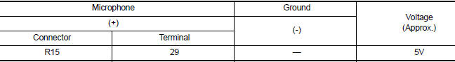
Is the voltage reading as specified?
YES >> GO TO 3
NO >> Replace Bluetooth control unit. Refer to AV"Removal and Installation".
3.CHECK MICROPHONE SIGNAL
Check signal between terminals of Bluetooth control unit connector B33.
Were voltage readings as specified?
YES >> Replace Bluetooth control unit. Refer to AV "Removal and Installation".
NO >> Replace microphone. Refer to AV "Removal and Installation".
 Bluetooth control signal circuit
Diagnosis Procedure Regarding Wiring Diagram information, refer to AV "Wiring Diagram". 1.CHECK CONTROL SIGNAL CIRCUIT CONTINUITY 1. Turn ignition switch OFF. 2. Disconnect Bluetooth con ...
Steering switch
Diagnosis Procedure Regarding Wiring Diagram information, refer to AV "Wiring Diagram". 1.CHECK STEERING WHEEL AUDIO CONTROL SWITCH RESISTANCE 1. Turn ignition switch OFF. 2. Disconnect ...
Other materials:
Doors
When the doors are locked using one of the
following methods, the doors cannot be opened
using the inside or outside door handles. The
doors must be unlocked to open the doors.
WARNING
Before opening any door, always look
for and avoid oncoming traffic.
To help avoid risk of injury or de ...
P0507 ISC system
Description
The ECM controls the engine idle speed to a specified level through the fine
adjustment of the air, which is let
into the intake manifold, by operating the electric throttle control actuator.
The operating of the throttle valve is
varied to allow for optimum control of the engine ...
Categories
- Manuals Home
- Nissan Versa Owners Manual
- Nissan Versa Service Manual
- Video Guides
- Questions & Answers
- External Resources
- Latest Updates
- Most Popular
- Sitemap
- Search the site
- Privacy Policy
- Contact Us

0.0071