Nissan Versa (N17): Line pressure control
Line pressure control : system diagram

Line pressure control : system description
- When an engine and A/T integrated control signal (engine torque)
equivalent to the engine drive force is
transmitted from the ECM to the TCM, the TCM controls the line pressure
solenoid valve.
This line pressure solenoid controls the pressure regulator valve as the signal pressure and adjusts the pressure of the operating oil discharged from the oil pump to the line pressure most appropriate to the driving state.
- The TCM has stored in memory a number of patterns for the optimum line pressure characteristic for the driving state.
- In order to obtain the most appropriate line pressure characteristic to meet the current driving state, the TCM controls the line pressure solenoid current value and thus controls the line pressure.
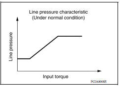
Normal Control
Each clutch is adjusted to the necessary pressure to match the engine drive force.
Back-up Control (Engine Brake)
When the select operation is performed during driving and the A/T is shifted down, the line pressure is set according to the vehicle speed.

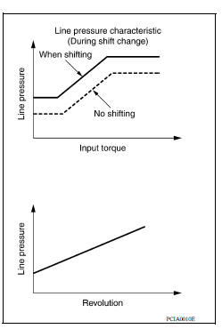
During Shift Change
The necessary and adequate line pressure for shift change is set.
For this reason, line pressure pattern setting corresponds to engine torque and gearshift selection. Also, line pressure characteristic corresponds to engine speed, during engine brake operation.
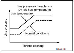
At Low Fluid Temperature
When the A/T fluid temperature drops below the prescribed temperature, in order to speed up the action of each friction element, the line pressure is set higher than the normal line pressure characteristic.
 A/T control system
A/T control system : system diagram ...
Shift change control
Shift change control : system diagram Shift change control : system description The clutch is controlled with the optimum timing and oil pressure by the engine speed, engine torque infor ...
Other materials:
Owner's Manual/Service Manual order information
Genuine NISSAN Service Manuals for this model
year and prior can be purchased. A Genuine
NISSAN Service Manual is the best source of
service and repair information for your vehicle.
This manual is the same one used by the factorytrained
technicians working at NISSAN dealerships.
Genuine NI ...
Floor trim
Exploded View
1. Harness clip A 2. Harness clip B 3. Floor carpet
4. Carpet hook 5. Front floor spacer (RH) 6. Front floor spacer (LH)
7. Rear floor spacer (LH) 8. Rear floor spacer (RH)
Front
Clip
Removal and Installation
REMOVAL
Remove front seat assemblies (LH/RH). Refer to SE &q ...
Categories
- Manuals Home
- Nissan Versa Owners Manual
- Nissan Versa Service Manual
- Video Guides
- Questions & Answers
- External Resources
- Latest Updates
- Most Popular
- Sitemap
- Search the site
- Privacy Policy
- Contact Us

0.0049