Nissan Versa (N17): Glove box assembly and housing
Removal and Installation
REMOVAL
1. Remove glove box lid.
a. Open glove box lid.
b. Pull glove box lid rearward and glove box lid hinges down and rearward to disengage, then remove the glove box lid.
c. Disconnect glove box damper (if equipped).
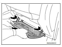
2. Remove glove box assembly.
a. Remove glove box assembly screws (A).
b. Pull glove box assembly rearward to disengage pawls and remove glove box assembly.
 : Pawl

INSTALLATION
Installation is in the reverse order of removal.
 Instrument lower panel LH
Removal and Installation REMOVAL Remove data link connector from instrument lower panel LH. Remove hood and fuel filler handle assembly bolts (A) and position hood and fuel filler handle as ...
Center console assembly
Exploded View 1. M/T console boot (M/T models) 2. Center console assembly Removal and Installation REMOVAL Move shift selector to "N" position (CVT models or A/T models). Remove shift ...
Other materials:
Spark plugs
Replacing spark plugs
Platinum-tipped spark plugs
It is not necessary to replace platinum-tipped A
spark plugs as frequently as conventional type
spark plugs because they last much longer. Follow
the maintenance log shown in the Maintenance
and Schedules section of this manual. Do
not ser ...
Front power window switch
Removal and Installation
REMOVAL
1. Remove front power window and door lock/unlock switch (RH)
finisher assembly using a suitable tool (A).
Pawl
2. Disconnect the harness connector from the front power window and door
lock/unlock switch (RH).
3. Separate front power window and door lock/ ...
Categories
- Manuals Home
- Nissan Versa Owners Manual
- Nissan Versa Service Manual
- Video Guides
- Questions & Answers
- External Resources
- Latest Updates
- Most Popular
- Sitemap
- Search the site
- Privacy Policy
- Contact Us

0.0047