Nissan Versa (N17): Front seat
DRIVER SIDE
DRIVER SIDE : Exploded View
WITH REMOVABLE HEADREST

1. Armrest (if equipped) 2. Seat cushion outer finisher (RH) 3. Seat belt buckle 4. Seat cushion trim 5. Seat cushion pad 6. Seat cushion frame 7. Seat cushion outer finisher (LH) 8. Lift lever (if equipped) 9. Lift lever cap (if equipped) 10. Recline lever 11. Side air bag module 12. Chute rod 13. Headrest holder (locked) 14. Seat frame assembly 15. Headrest holder (free) 16. Headrest 17. Seatback pad 18. Seatback trim
WITHOUT REMOVABLE HEADREST
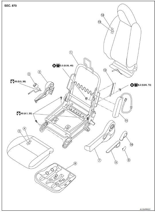
1. Seat frame assembly 2. Seat cushion outer finisher (RH) 3. Seat belt buckle 4. Seat cushion trim 5. Seat cushion pad 6. Seat cushion frame 7. Seat cushion outer finisher (LH) 8. Lift lever (if equipped) 9. Lift lever cap (if equipped) 10. Recline lever 11. Side air bag module 12. Chute rod 13. Seatback pad 14. Seatback trim
Driver side : Disassembly and Assembly
SEATBACK ASSEMBLY
WARNING: Do not leave any objects (screwdrivers, tools, etc.) on the seat during seatback repair. It can lead to personal injury if the side air bag should accidentally deploy.
CAUTION:
- Before servicing, turn ignition switch OFF, disconnect both battery terminals and wait at least three minutes.
- Handle the side air bag module carefully. During disassembly, always hold the side air bag module, do not let it hang by the wire harness.
- Always work from the side or back of the seatback assembly, do not work in front of seat.
- Do not use air tools or electric tools for servicing the seat assembly.
- Replace the side air bag module if it has been dropped or sustained an impact.
- Do not insert any objects into the side air bag module.
- Do not attempt to disassemble the side air bag module.
- Do not expose the side air bag module to temperatures exceeding 93C (200F).
- Do not expose the side air bag module to any oil, grease, detergent or water.
- During disassembly, do not damage the seatback board, chutes, connectors, retainers, clips, module harness or the side air bag module.
NOTE: If the vehicle has been involved in a collision and the side air bag module has deployed, the front seatback assembly must be replaced.
Disassembly
- Remove the front seat assembly. Refer to SE "DRIVER SIDE : Removal and Installation".
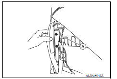
- Release the lower seatback trim retainer strap (A) from the seat cushion frame.

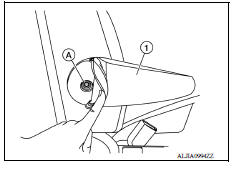
3. Remove the armrest (1) (if equipped).
a. Unzip the armrest to access the armrest bolt (A).
b. Remove the armrest bolt (A) and the armrest (1).

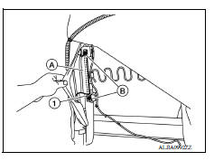
4. Release the J-hook retainer (C), unzip seatback zipper (A) and release J-clips (B) holding the seatback trim to the seat frame assembly.

5. Reach up through the seatback trim and release locks as shown and remove the headrest holders (if equipped).
CAUTION: Before removing/installing the headrest holder, check its orientation (front/rear and right/left)

6. Remove and discard the two chute rod nuts (B), then route the chute rod (1) through the opening and remove it from the chute (A).
CAUTION: Do not reuse the chute rod nuts.

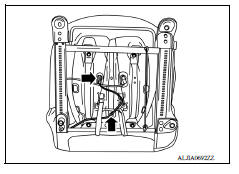
7. Release the side air bag module harness from the seat frame assembly.
NOTE: Take note of harness routing and attachment location for accurate installation.
a. From the back of the seat unclip the side air bag module harness
clips ( ).
).

b. From the bottom of the seat unclip the side air bag module harness
clips ( ).
).

8. Remove and discard the two side air bag module nuts (A).
CAUTION: Do not reuse the side air bag module nuts.

9. Disengage the side air bag module studs from the seatback frame and lift the seatback trim and seatback pad as an assembly from the seat frame assembly.
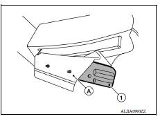
10. Pull the side air bag module (1) out of the chute (A) and remove from the seatback trim.

CAUTION:
- Replace the side air bag module if it has been dropped or sustained an impact.
- Do not strike the side air bag module.

11. Separate the seatback trim from the seatback pad.
a. For seatback with removable headrest.
i. Remove the hog rings and separate the seatback trim (1) from the seatback pad.
 : Hog ring
NOTE: Remove all pieces of hog rings and discard them.

b. For seatback without removable headrest.
i. Remove the hog rings and separate the seatback trim (1) from the seatback pad.
: Hog ring
NOTE: Remove all pieces of hog rings and discard them.

Assembly
Assembly is in the reverse order of disassembly.
- Tighten the side air bag module nuts to specification. Refer to SE "DRIVER SIDE : Exploded View".
CAUTION: Do not reuse the side air bag module nuts.
- Tighten the chute rod nuts to specification. Refer to SE "DRIVER SIDE : Exploded View".
CAUTION: Do not reuse the chute rod nuts.
CAUTION:
- Inspect seatback pad, seatback trim and seatback trim chutes. Replace if damaged.
- Smooth out all wrinkles during assembly.
- Always route side air bag module harness in original location. Replace any deformed or damaged clips with same type and color. Always install clips in the original location in the harness.
- After work is completed, check that no system malfunction is detected causing the air bag warning lamp to illuminate.
- If a malfunction is detected by the air bag warning lamp after repair or replacement of the malfunction parts, perform the SRS final check. Refer to SRC "SRS Final Check".
- Install new hog rings on the seatback trim in original positions.
Use only one hog ring in each designated location.
Ensure hog rings are correctly fastened around both the seatback trim and seatback pad wires.
Use NISSAN standard hog rings and tools to assemble.

SEAT CUSHION
WARNING: Do not leave any objects (screwdrivers, tools, etc.) on the seat during seat cushion repair. It can lead to personal injury if the side air bag should accidentally deploy.
CAUTION:
- Before servicing, turn ignition switch OFF, disconnect both battery terminals and wait at least three minutes.
- Always work from the side or back of the seatback assembly, do not work in front of seat.
- Do not use air tools or electric tools for servicing the seat assembly.
- During disassembly, do not damage the seatback cover, chutes, connectors, retainers, clips, module harness or the side air bag module.
Disassembly
- Remove the front seat assembly. Refer to SE "DRIVER SIDE : Removal and Installation".
- Remove the lift lever.
a. Release pawls and remove the lift lever cap (1) (if equipped).
b. Remove screws and the lift lever (2) (if equipped).
 : Pawl

3. Remove the recline lever.
a. Remove snap ring (1) using a suitable tool, then the recline lever (2).

4. Remove the seat cushion outer finisher (LH).
a. Remove the screw (A).
b. Release the metal clips, then remove the seat cushion outer finisher (LH) (1).
 : Metal clip

5. Remove the seat belt buckle.
a. Unclip the seat belt buckle harness clip and connector clip from seat frame assembly.
b. Remove the seat belt buckle anchor bolt and the seat belt buckle.
6. Remove the seat cushion outer finisher (RH).
a. Remove the screw (B).
b. Lift up seat cushion trim (A).
c. Slide seat cushion outer finisher (RH) (1) rearward to release pawl and remove.
 : Pawl

7. Remove the seat cushion assembly from the seat frame assembly.
a. Release the seatback trim J-clips (C) and seat cushion J-clips (B) from the seat cushion frame.
b. Unclip the harness from the seat cushion frame.
NOTE: Take note of harness routing and attachment location for accurate installation.
c. Remove bolts (A) and the seat cushion assembly.

8. Remove seat cushion trim and seat cushion pad as an assembly from the seat cushion frame:
a. Release string at locations (A) from seat cushion frame (1).
 : Front
b. Loosen string and remove the seat cushion pad and seat cushion trim.

9. Separate the seat cushion trim from the seat cushion pad.
a. Remove the hog rings and separate the seat cushion trim (1) from the seat cushion pad.
 : Hog ring
NOTE: Remove all pieces of hog rings and discard them.

Assembly
Assembly is in the reverse order of disassembly.
CAUTION:
- Smooth out all wrinkles during assembly.
- Always route side air bag module harness in original location. Replace any deformed or damaged clips with same type and color. Always install clips in the original location in the harness.
- After work is completed, check that no system malfunction is detected causing the air bag warning lamp to illuminate.
- If a malfunction is detected by the air bag warning lamp after repair or replacement of the malfunction parts, perform the SRS final check. Refer to SRC "SRS Final Check".
- Install new hog rings on the seat cushion trim in original positions.
Use only one hog ring in each designated location.
Ensure hog rings are correctly fastened around both the seat cushion trim and seat cushion pad wires.
Use NISSAN standard hog rings and tools to assemble.

Driver side : Disassembly and Assembly - Side Air Bag Module
DISASSEMBLY
WARNING: Do not leave any objects (screwdrivers, tools, etc.) on the seat during seatback repair. It can lead to personal injury if the side air bag should accidentally deploy.
CAUTION:
- Before servicing the side air bag module, turn ignition switch OFF, disconnect both battery terminals and wait at least three minutes.
- Handle the side air bag module carefully. During disassembly, always hold the side air bag module, do not let it hang by the wire harness.
- Always work from the side or back of the seatback assembly, do not work in front of seat.
- Do not use air tools or electric tools for servicing the seat assembly.
- Replace the side air bag module if it has been dropped or sustained an impact.
- Do not insert any objects into the side air bag module.
- Do not attempt to disassemble the side air bag module.
- Do not expose the side air bag module to temperatures exceeding 93C (200F).
- Do not expose the side air bag module to any oil, grease, detergent or water.
- During disassembly, do not damage the seatback board, chutes, connectors, retainers, clips, module harness or the side air bag module.
NOTE:
- If the vehicle has been involved in a collision and the side air bag module has deployed, the front seatback assembly must be replaced.
- For side air bag module removal and installation, seatback trim and seatback pad must be removed.
- Remove the front seat assembly. Refer to SE "DRIVER SIDE : Removal and Installation".
- Release the lower seatback trim retainer strap (A) from the seat cushion frame.

3. Remove the armrest (1) (if equipped).
a. Unzip the armrest to access the armrest bolt (A).
b. Remove the armrest bolt (A) and the armrest (1).
4. Release the J-hook retainer (C), unzip seatback zipper (A) and release J-clips (B) holding the seatback trim to the seat frame assembly.

5. Reach up through seatback trim and release locks as shown and remove the headrest holders (if equipped).
CAUTION: Before removing/installing the headrest holder, check its orientation (front/rear and right/left)
6. Remove and discard the two chute rod nuts (B), then route the chute rod (1) through the opening and remove it from the chute (A).
CAUTION: Do not reuse the chute rod nuts.
7. Release the side air bag module harness from seat frame assembly.
NOTE: Take note of harness routing and attachment location for accurate installation.
a. From the back of the seat unclip the side air bag module harness
clips (  ).
).

b. From the bottom of the seat unclip the side air bag
module harness
clips ( ).
).
8. Remove and discard the two side air bag module nuts (A).
CAUTION: Do not reuse the side air bag module nuts.
9. Disengage the side air bag module studs from the seatback frame and lift the seatback trim and seatback pad as an assembly from the seat frame assembly.
10. Pull the side air bag module (1) out of the chute (A) and remove from the seatback trim.
CAUTION:
- Replace the side air bag module if it has been dropped or sustained an impact.
- Do not strike the side air bag module.

ASSEMBLY
Assembly is in the reverse order of disassembly.
- Tighten the side air bag module nuts to specification. Refer to SE "DRIVER SIDE : Exploded View".
CAUTION: Do not reuse the side air bag module nuts.
- Tighten the chute rod nuts to specification. Refer to SE "DRIVER SIDE : Exploded View".
CAUTION: Do not reuse the chute rod nuts.
CAUTION:
- Inspect seatback pad, seatback trim and seatback trim chutes. Replace if damaged.
- Smooth out all wrinkles during assembly.
- Always route side air bag module harness in original location. Replace any deformed or damaged clips with same type and color. Always install clips in the original location in the harness.
- After work is completed, check that no system malfunction is detected causing the air bag warning lamp to illuminate.
- If a malfunction is detected by the air bag warning lamp after repair or replacement of the malfunction parts, perform the SRS final check. Refer to SRC "SRS Final Check".
 Rear seat
Exploded View - Fixed Seatback FIXED SEATBACK 1. Headrest holder (locked) 2. Headrest holder (free) 3. Rear seatback assembly 4. Seatback trim 5. Seatback pad 6. LATCH bracket (RH) 7. Seat c ...
Passenger side
PASSENGER SIDE : Exploded View WITH REMOVABLE HEADREST 1. Seatback trim 2. Seatback pad 3. Headrest 4. Headrest holder (free) 5. Headrest holder (locked) 6. Chute rod 7. Seat frame assembly 8. ...
Other materials:
Vehicle Dynamic Control (VDC) system (if so equipped)
The VDC system uses various sensors to monitor
driver inputs and vehicle motion. Under certain
driving conditions, the VDC System helps to perform
the following functions:
Controls brake pressure to reduce wheel
slip on one slipping drive wheel so power is
transferred to a non slipping drive w ...
Mixture ratio selflearning value
clear
Description
This describes how to erase the mixture ratio selflearning value. For the
actual procedure, follow the instructions
in "Diagnosis Procedure".
Work Procedure
1.START
With CONSULT
Start engine and warm it up to normal operating temperature.
Select "SELFLEARNING CONT" in "WOR ...
Categories
- Manuals Home
- Nissan Versa Owners Manual
- Nissan Versa Service Manual
- Video Guides
- Questions & Answers
- External Resources
- Latest Updates
- Most Popular
- Sitemap
- Search the site
- Privacy Policy
- Contact Us

0.0081