Nissan Versa (N17): Diagnosis and repair workflow
Work Flow (With EXP-800 NI or GR8-1200 NI)
CHARGING SYSTEM DIAGNOSIS WITH EXP-800 NI OR GR8-1200 NI
To test the charging system, use the following special service tools:
- EXP-800 NI Battery and electrical diagnostic analyzer
- GR8-1200 NI Multitasking battery and electrical diagnostic station
NOTE: Refer to the applicable Instruction Manual for proper charging system diagnosis procedures.
OVERALL SEQUENCE

DETAILED FLOW
NOTE: To ensure a complete and thorough diagnosis, the battery, stater and generator test segments must be done as a set from start to finish.
1.PRELIMINARY INSPECTION
Perform the preliminary inspection. Refer to CHG "Diagnosis Procedure".
>> GO TO 2.
2.STOP POWER GENERATION VOLTAGE VARIABLE CONTROL SYSTEM
Stop the operation of the power generation voltage variable control in either of the following procedures.
- After selecting "ENGINE" using CONSULT, set the DUTY value of "ALTERNATOR DUTY" to 0 % by selecting "ALTERNATOR DUTY" of "Active Test". Continue "Active Test" until the end of inspection. (When the DUTY value is 0 or 100 %, the normal power generation is performed according to the characteristic of the IC regulator of the generator.)
- Turn the ignition switch OFF, and disconnect the battery current sensor connector. [However, DTC (P1550- P1554) of the engine might remain. After finishing the inspection, connect the battery current sensor connector and erase the self diagnosis results history of the engine using CONSULT.]
>> GO TO 3.
3.DIAGNOSIS WITH EXP-800 NI OR GR8-1200 NI
Perform the charging system test using Multitasking battery and electrical diagnostic station GR8-1200 NI or Battery and electrical diagnostic analyzer EXP-800 NI. Refer to the applicable Instruction Manual for proper testing procedures.
Test result
NO PROBLEMS>>Charging system is normal and will also show "DIODE RIPPLE" test result.
NO VOLTAGE>>GO TO 4.
LOW VOLTAGE>>GO TO 12.
HIGH VOLTAGE>>GO TO 14.
EXCESSIVE RIPPLE, OPEN PHASE, OPEN DIODE or SHORTED DIODE>>Replace the generator. Refer to CHG "Removal and Installation". Perform "DIODE RIPPLE" test again using Multitasking battery and electrical diagnostic station GR8-1200 NI or Battery and electrical diagnostic analyzer EXP-800 NI to confirm repair.
4.INSPECTION WITH CHARGE WARNING LAMP (IGNITION SWITCH IS ON)
Turn the ignition switch ON.
Does the charge warning lamp illuminate?
YES >> GO TO 6.
NO >> GO TO 5.
5."L" TERMINAL CIRCUIT (OPEN) INSPECTION
Check "L" terminal circuit (open). Refer to CHG "Diagnosis Procedure".
Is the "L" terminal circuit normal?
YES >> Replace generator. Refer to CHG "Removal and Installation".
NO >> Repair as needed.
6.INSPECTION WITH CHARGE WARNING LAMP (IDLING)
Start the engine and run it at idle.
Does the charge warning lamp turn OFF?
YES >> GO TO 9.
NO >> GO TO 7.
7."L" TERMINAL CIRCUIT (SHORT) INSPECTION
Check "L" terminal circuit (short). Refer to CHG "Diagnosis Procedure".
Is the "L" terminal circuit normal?
YES >> GO TO 8.
NO >> Repair as needed.
8."S" TERMINAL CIRCUIT INSPECTION
Check "S" terminal circuit. Refer to CHG "Diagnosis Procedure".
Is the "S" terminal circuit normal?
YES >> GO TO 10.
NO >> Repair as needed.
9.INSPECTION WITH CHARGE WARNING LAMP (ENGINE AT 3,000 RPM)
Increase and maintain the engine speed at 3,000 rpm.
Does the charge warning lamp remain off?
YES >> GO TO 11.
NO >> GO TO 10.
10.INSPECTION OF GENERATOR PULLEY
Check generator pulley. Refer to CHG"Removal and Installation".
Is generator pulley normal?
YES >> Replace generator. Refer to CHG "Removal and Installation".
NO >> Repair as needed.
11."B" TERMINAL CIRCUIT INSPECTION
Check "B" terminal circuit. Refer to CHG "Diagnosis Procedure".
Is "B" terminal circuit normal?
YES >> Replace generator. Refer to CHG "Removal and Installation".
NO >> Repair as needed.
12."B" TERMINAL CIRCUIT INSPECTION
Check "B" terminal circuit. Refer to CHG "Diagnosis Procedure".
Is "B" terminal circuit normal?
YES >> GO TO 13.
NO >> Repair as needed.
13.INSPECTION OF GENERATOR PULLEY
Check generator pulley. Refer to CHG "Removal and Installation".
Is generator pulley normal?
YES >> Replace generator. Refer to CHG"Removal and Installation".
NO >> Repair as needed.
14."S" TERMINAL CIRCUIT INSPECTION
Check "S" terminal circuit. Refer to CHG "Diagnosis Procedure".
Is the "S" terminal circuit normal?
YES >> Replace generator. Refer to CHG "Removal and Installation".
NO >> Repair as needed.
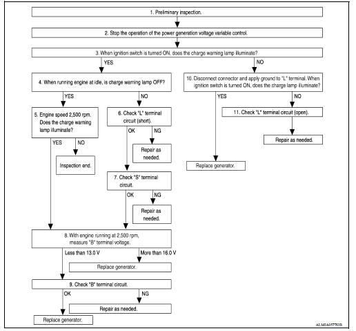
Work Flow (Without EXP-800 NI or GR8-1200 NI)
OVERALL SEQUENCE
Before performing a generator test, make sure that the battery is fully charged. A 30-volt voltmeter and suitable test probes are necessary for the test.
- Before starting, inspect the fusible link.
- Use fully charged battery.
DETAILED FLOW
1.PRELIMINARY INSPECTION
Perform the preliminary inspection. Refer to CHG "Diagnosis Procedure".
>> GO TO 2.
2.STOP POWER GENERATION VOLTAGE VARIABLE CONTROL SYSTEM
Stop the operation of the power generation voltage variable control in either of the following procedures:
- After selecting "ENGINE" using CONSULT, set the DUTY value of "ALTERNATOR DUTY" to 0 % by selecting "ALTERNATOR DUTY" with "Active Test". Continue "Active Test" until the end of inspection. (When the DUTY value is 0 or 100 %, the normal power generation is performed according to the characteristic of the IC regulator of the generator.)
- Turn the ignition switch OFF, and disconnect the battery current sensor connector. [However, DTC (P1550 - P1554) of the engine might remain. After finishing the inspection, connect the battery current sensor connector and erase the self-diagnostic results history of the engine using CONSULT.]
>> GO TO 3.
3.INSPECTION WITH CHARGE WARNING LAMP (IGNITION SWITCH IS TURNED ON)
When ignition switch is turned ON.
Does the charge warning lamp illuminate?
YES >> GO TO 4.
NO >> GO TO 10.
4.INSPECTION WITH CHARGE WARNING LAMP (IDLING)
Start the engine and run it at idle
Does the charge warning lamp turn OFF?
YES >> GO TO 5.
NO >> GO TO 6.
5.INSPECTION WITH CHARGE WARNING LAMP (ENGINE AT 2,500 RPM)
Increase and maintain the engine speed at 2,500 rpm.
Does the charge warning lamp illuminate?
YES >> GO TO 8.
NO >> Inspection End.
6."L" TERMINAL CIRCUIT (SHORT) INSPECTION
Check terminal "L" circuit for (short). Refer to CHG "Diagnosis Procedure".
Is the inspection result normal?
YES >> GO TO 7.
NO >> Repair as needed.
7."S" TERMINAL CIRCUIT INSPECTION
Check terminal "S" circuit. Refer to CHG "Diagnosis Procedure".
Is the inspection result normal?
YES >> GO TO 8.
NO >> Repair as needed.
8.MEASURE "B" TERMINAL VOLTAGE
Start engine. With engine running at 2,500 rpm, measure "B" terminal voltage.
What voltage does the measurement result show?
Less than 13.0 V>>GO TO 9.
More than 16.0 V>>Replace generator. Refer to CHG "Removal and Installation".
9."B" TERMINAL CIRCUIT INSPECTION
Check "B" terminal circuit. Refer to CHG "Diagnosis Procedure".
Is the inspection result normal?
YES >> Replace generator. Refer to CHG "Removal and Installation".
NO >> Repair as needed.
10.INSPECTION WITH CHARGE WARNING LAMP (IGNITION SWITCH IS ON)
1. Disconnect generator connector and apply ground to "L" terminal.
2. Turn the ignition switch ON.
Does the charge warning lamp illuminate?
YES >> Replace generator. Refer to CHG "Removal and Installation".
NO >> GO TO 11.
11.CHECK "L" TERMINAL CIRCUIT (OPEN)
Check "L" terminal circuit (OPEN). Refer to CHG "Diagnosis Procedure".
>> Repair as needed.
DTC/CIRCUIT DIAGNOSIS
 System
CHARGING SYSTEM CHARGING SYSTEM : System Diagram CHARGING SYSTEM : System Description The generator provides DC voltage to operate the vehicle's electrical system and to keep the battery ch ...
Charging system preliminary inspection
Diagnosis Procedure 1.CHECK BATTERY TERMINALS CONNECTION Check if battery terminals are clean and tight. Is the inspection result normal? YES >> GO TO 2. NO >> Repair battery termin ...
Other materials:
Child safety
WARNING
Do not allow children to play with the seat
belts. Most seating positions are
equipped with Automatic Locking Retractor
(ALR) mode seat belts. If the seat belt
becomes wrapped around a child's neck
with the ALR mode activated, the child can
be seriously injured or killed if the seat
...
Service data and specifications
(SDS)
General Specification
CAUTION:
Use only Genuine NISSAN Matic S ATF. Do not mix with other ATF.
Using ATF other than Genuine NISSAN Matic S ATF will cause
deterioration of driveability and A/T durability, and may damage
the A/T, which is not covered by the warranty.
*1: ...
Categories
- Manuals Home
- Nissan Versa Owners Manual
- Nissan Versa Service Manual
- Video Guides
- Questions & Answers
- External Resources
- Latest Updates
- Most Popular
- Sitemap
- Search the site
- Privacy Policy
- Contact Us

0.0073