Nissan Versa (N17): Cruise control (if so equipped)
Precautions on cruise control
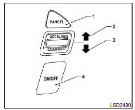
1. CANCEL switch
2. ACCEL/RES switch
3. COAST/SET switch
4. CRUISE ON/OFF switch
- If the cruise control system malfunctions, it cancels automatically.
- To properly set the cruise control system, use the following procedures.
WARNING
Do not use the cruise control when driving under the following conditions:
- When it is not possible to keep the vehicle at a set speed.
- In heavy traffic or in traffic that varies in speed.
- On winding or hilly roads.
- On slippery roads (rain, snow, ice, etc.).
- In very windy areas.
Doing so could cause a loss of vehicle control and result in an accident.
CAUTION
On manual transmission models, do not shift into N (Neutral) without depressing the clutch pedal when the cruise control is set. Should this occur, depress the clutch pedal and turn the main switch off immediately.
Failure to do so may cause engine damage.
Cruise control operations
The cruise control allows driving at a speed between 25 - 89 mph (40 - 144 km/h) without keeping your foot on the accelerator pedal.
To turn on the cruise control, push the CRUISE ON/OFF switch. The CRUISE indicator light in the instrument panel comes on.
To set cruising speed, accelerate the vehicle to the desired speed, push the COAST/SET switch and release it. The CRUISE indicator light in the instrument panel comes on. Take your foot off the accelerator pedal. Your vehicle maintains the set speed.
- To pass another vehicle, depress the accelerator pedal. When you release the pedal, the vehicle returns to the previously set speed.
- The vehicle may not maintain the set speed when going up or down steep hills. If this happens, drive without the cruise control.
To cancel the preset speed, use one of the following three methods.
- Push the CANCEL switch; the CRUISE indicator light in the instrument panel goes out.
- Tap the brake pedal; the CRUISE indicator light goes out.
- Push the CRUISE ON/OFF switch off. The CRUISE indicator light in the instrument panel goes out.
The cruise control is automatically canceled and the CRUISE light in the instrument panel goes out if:
- you depress the brake or clutch pedal while pushing the ACCEL/RES or SET/COAST switch. The preset speed is deleted from memory.
- the vehicle slows down more than 8 mph (13 km/h) below the set speed.
- you depress the clutch pedal (manual transmission), or move the shift lever into N (Neutral) (CVT).
To reset at a faster cruising speed, use one of the following three methods.
- Depress the accelerator pedal. When the vehicle attains the desired speed, push and release the COAST/SET switch.
- Push and hold the ACCEL/RES switch.
When the vehicle attains the speed you desire, release the switch.
- Push and release the ACCEL/RES switch.
Each time you do this, the set speed increases by about 1 mph (1.6 km/h).
To reset at a slower cruising speed, use one of the following three methods.
- Lightly tap the brake pedal. When the vehicle attains the desired speed, push the COAST/SET switch and release it.
- Push and hold the COAST/SET switch. Release the switch when the vehicle slows to the desired speed.
- Push and release the COAST/SET switch.
Each time you do this, the set speed decreases by about 1 mph (1.6 km/h).
To resume the preset speed, push and release the ACCEL/RES switch. The vehicle returns to the last set cruising speed when the vehicle speed is over 25 mph (40 km/h).
 Parking brake
WARNING Be sure the parking brake is fully released before driving. Failure to do so can cause brake failure and lead to an accident. Do not release the parking brake from outside the ve ...
Break-in schedule
CAUTION During the first 1,200 miles (2,000 km), follow these recommendations to obtain maximum engine performance and ensure the future reliability and economy of your new vehicle. Failure to fo ...
Other materials:
Oil cooler
Exploded View
1. Radiator hose (upper) 2. Hose clamp 3. Radiator hose (lower)
4. Hose clamp 5. Water hose 6. Oil cooler
7. Connector bolt 8. Water hose 9. Oring
A. To radiator (upper side) B. To radiator (lower side) 10. Relief valve
Removal and Installation
REMOVAL
NOTE:
When removing co ...
Fuel level sensor unit, fuel filter and fuel pump assembly
Exploded View
1. Lock ring 2. Fuel level sensor unit, fuel filter and
fuel pump assembly
3. O-ring
4. Fuel tank
Removal and Installation
WARNING:
Be sure to read "General Precautions" before working on the fuel system. Refer
to FL, "General Precautions".
REMOVAL
Release t ...
Categories
- Manuals Home
- Nissan Versa Owners Manual
- Nissan Versa Service Manual
- Video Guides
- Questions & Answers
- External Resources
- Latest Updates
- Most Popular
- Sitemap
- Search the site
- Privacy Policy
- Contact Us

0.0074