Nissan Versa (N17): Component parts
Component Parts Location

1. Crash zone sensor 2. Front door satellite sensor LH 3. Spiral cable 4. Front passenger air bag off indicator 5. Front LH seatbelt pre-tensioner Side air bag satellite sensor LH 6. Air bag diagnosis sensor unit 7. Front LH side air bag module 8. Seat belt buckle switch (LH) Seat belt buckle switch (RH) 9. Occupant classification system control unit and sensors 10. Front RH seatbelt pre-tensioner Side air bag satellite sensor RH 11. Front RH side air bag module 12. RH side curtain air bag module 13. Front door satellite sensor RH 14. LH side curtain air bag module 15. Front passenger air bag module 16. Driver air bag module
Component Description
|
Component |
Function |
| Air bag diagnosis sensor unit | Refer to SRC "Air Bag Diagnosis Sensor Unit". |
| Driver air bag module | Refer to SRC "Driver Air Bag Module". |
| Front passenger air bag module | Refer to SRC "Front Passenger Air Bag Module". |
| Front side air bag module | Refer to SRC "Front Side Air Bag Module". |
| Side curtain air bag module | Refer to SRC "Side Curtain Air Bag Module". |
| Front seat belt pre-tensioner | Refer to SRC "Front Seat Belt Pre-tensioner". |
| Occupant classification system | Refer to SRC "OCCUPANT CLASSIFICATION SYSTEM : System Description". |
| Crash zone sensor | Refer to SRC "Crash Zone Sensor". |
| Side air bag (satellite) sensor | Refer to SRC "Side Air Bag Satellite Sensor". |
| Front door (satellite) sensor | Refer to SRC "Door Satellite Sensor". |
| Seat belt buckle switch | The seat belt buckle switches (LH/RH) provide the seat belt buckle signals to the air bag diagnosis sensor unit and the combination meter. |
| Spiral cable | The spiral cable provides a rotating physical connection to the driver air bag module. |
| Combination meter | The combination meter displays the air bag warning lamp and the seat belt warning lamp. The air bag warning lamp is used for diagnosis in User Mode and may be used to display diagnostic trouble codes without the use of the CONSULT. |
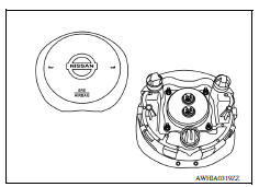
Driver Air Bag Module
The driver air bag module is dual stage and located in the steering wheel assembly. It operates with the SRS system in a frontal collision exceeding a specified level.
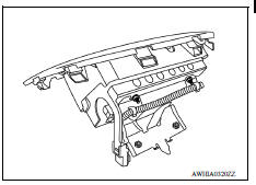
Front Passenger Air Bag Module
The front passenger air bag module is located behind the instrument panel assembly. It operates with the SRS system in a frontal collision exceeding a specified level. Refer to SRC "OCCUPANT CLASSIFICATION SYSTEM : System Description" for more information.
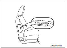
Front Side Air Bag Module
Front side air bag modules are built into the front seatback assemblies.
Vehicles with side air bags are equipped with labels as shown.
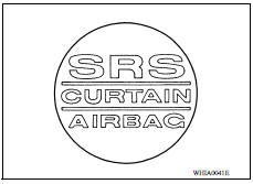
Side Curtain Air Bag Module
Side curtain air bag modules are located above the vehicle headlining.
Vehicles with side curtain air bags are equipped with labels on the center pillar upper finisher as shown.
Front Seat Belt Pre-tensioner
The seat belt pre-tensioner system with load limiter is installed for both the driver's seat and the front passenger's seat. It operates simultaneously with the SRS air bag system in the event of a frontal collision with an impact exceeding a specified level.
When the frontal collision with an impact exceeding a specified level occurs, seat belt slack resulting from clothing or other factors is immediately taken up by the pre-tensioner. Vehicle passengers are securely restrained.
When passengers in a vehicle are thrown forward in a collision and the restraining force of the seat belt exceeds a specified level, the load limiter permits the specified extension of the seat belt by the twisting of the ELR shaft, and a relaxation of the chest-area seat belt web tension while maintaining force.

Air Bag Diagnosis Sensor Unit
The air bag diagnosis sensor unit is located under the center console.
The air bag diagnosis sensor unit receives signals from multiple SRS sensors and controls the deployment of the air bags. The deployment of the air bags depends on the type and severity of the collision. The air bag diagnosis sensor unit has self-diagnosis capability through the use of the CONSULT as well as flash codes displayed by the air bag warning lamp.

Crash Zone Sensor
The crash zone sensor is located behind the front grille in front of the radiator support. The crash zone sensor sends signals to the air bag diagnosis sensor unit during a frontal collision. This sensor may be identified by a yellow connector.

Side Air Bag Satellite Sensor
The side air bag satellite sensors are located on the center pillar LH and RH next to the seat belt pretensioners. The side air bag satellite sensors send signals to the air bag diagnosis sensor unit during a side collision. These sensors may be identified by yellow connectors.

Door Satellite Sensor
The front door satellite sensors are located in the driver and passenger doors. The front door satellite sensors send signals to the air bag diagnosis sensor unit during a side collision. These sensors may be identified by yellow connectors.

SRS Component Connectors
DIRECT CONNECT
The following SRS components use direct-connect style harness connectors.
- Driver front air bag module
- Passenger front air bag module
- LH side curtain air bag module
- RH side curtain air bag module
- Front LH seat belt pre-tensioner
- Front RH seat belt pre-tensioner
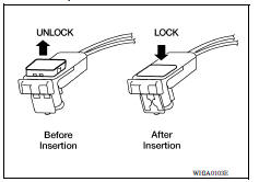
Always pull up to release locking tab prior to removing connector from SRS component.
Always push down to lock locking tab after installing connector to SRS component. When locked, the locking tab is level with the connector housing.
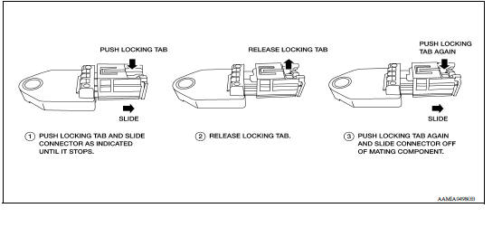
SLIDE DOUBLE LOCKING
- A new style slide double locking type connector is used on certain systems and components, especially those related to airbag control systems.
- The slide double locking type connectors help prevent incomplete locking and accidental looseness or disconnection.
- The slide double locking type connectors are disconnected by pushing or pulling the slider. Refer to the figure below.
CAUTION: Do not pull the harness or wires when disconnecting the connector.
SYSTEM
 Precautions
SRS Air bag system
SRS AIR BAG SYSTEM : System Diagram SRS AIR BAG SYSTEM : System Description The air bag deploys if the air bag diagnosis sensor unit is activated while the ignition switch is in the ON or ...
Other materials:
Valve oil seal
VALVE OIL SEAL : Removal and Installation
REMOVAL
Remove camshafts.
Remove valve lifters.
Rotate crankshaft, and set piston with valve oil seal to be removed to
TDC. This will prevent the valve
from dropping into cylinder.
CAUTION:
When rotating crankshaft, be careful to avoid ...
System (power door lock system)
System Diagram
System Description
DOOR LOCK FUNCTION
The door lock and unlock switch (driver side) is built into power window
main switch.
The door lock and unlock switch (passenger side) is on door trim.
Interlocked with the locking operation of door lock and unlock swit ...
Categories
- Manuals Home
- Nissan Versa Owners Manual
- Nissan Versa Service Manual
- Video Guides
- Questions & Answers
- External Resources
- Latest Updates
- Most Popular
- Sitemap
- Search the site
- Privacy Policy
- Contact Us

0.0088