 Nissan Versa Sedan Service ManualElectrical & power control » LAN System (LAN) » CAN Communication system
CAN Communication system : CAN System
Specification Chart
CAN Communication system : CAN System Specification Chart
Determine CAN system type from the following specification chart.
NOTE: Refer to LAN, "Trouble Diagnosis Procedure" for how to use CAN system specification chart.
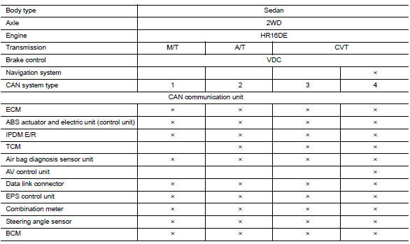
×: Applicable
VEHICLE EQUIPMENT IDENTIFICATION INFORMATION
NOTE: Check CAN system type from the vehicle shape and equipment.

1. NAVI switches A. With navigation system
CAN COMMUNICATION SYSTEM : CAN Communication Signal Chart
Refer to LAN "How to Use CAN Communication Signal Chart" for how to use CAN communication signal chart.
NOTE:
- Refer to LAN "Abbreviation List" for the abbreviations of the connecting units.
- The AV control unit uses CAN communication only for communicating with the diagnostic tool (not with other connected control units).


*: With battery current sensor (with battery temperature sensor)
NOTE: CAN data of the air bag diagnosis sensor unit is not used by usual service work, thus it is omitted.
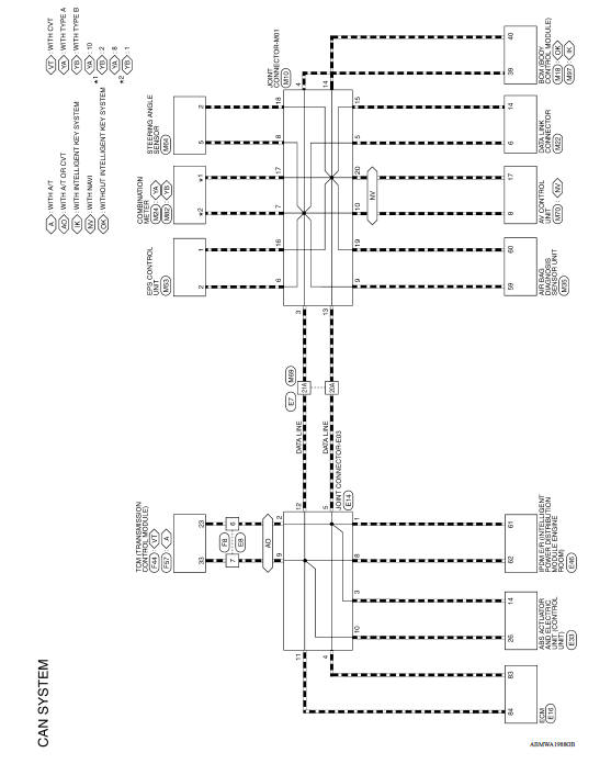
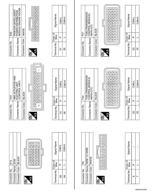
WIRING DIAGRAM
CAN SYSTEM
Wiring Diagram


BASIC INSPECTION
DIAGNOSIS AND REPAIR WORKFLOW
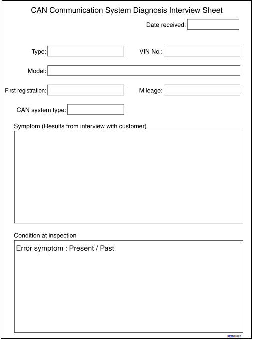
Interview Sheet
NOTE: Refer to LAN"Trouble Diagnosis Procedure" for how to use interview sheet.
DTC/CIRCUIT DIAGNOSIS
MALFUNCTION AREA CHART
Main Line
| Malfunction area | Reference |
| Main line between IPDM E/R and data link connector | LAN "Diagnosis Procedure" |
Branch Line
| Malfunction area | Reference |
| ECM branch line circuit | LAN "Diagnosis Procedure" |
| ABS actuator and electric unit (control unit) branch line circuit | LAN "Diagnosis Procedure" |
| IPDM E/R branch line circuit | LAN "Diagnosis Procedure" |
| TCM branch line circuit | LAN "Diagnosis Procedure" |
| Air bag diagnosis sensor unit branch line circuit | LAN "Diagnosis Procedure" |
| AV control unit branch line circuit | LAN "Diagnosis Procedure" |
| Data link connector branch line circuit | LAN"Diagnosis Procedure" |
| EPS control unit branch line circuit | LAN "Diagnosis Procedure" |
| Combination meter branch line circuit | LAN "Diagnosis Procedure" |
| Steering angle sensor branch line circuit | LAN "Diagnosis Procedure" |
| BCM branch line circuit | LAN "Diagnosis Procedure" |
Short Circuit
| Malfunction area | Reference |
| CAN communication circuit | LAN"Diagnosis Procedure" |
