Nissan Versa (N17): C1116 Stop lamp switch
DTC Logic
DTC DETECTION LOGIC

DTC CONFIRMATION PROCEDURE
1.CHECK SELF-DIAGNOSIS RESULTS
Check the self-diagnosis results.

Is above displayed on the self-diagnosis display?
YES >> Proceed to diagnosis procedure. Refer to BRC "Diagnosis Procedure".
NO >> Inspection End.
Diagnosis Procedure
Regarding Wiring Diagram information, refer to BRC "Wiring Diagram".
1.CONNECTOR INSPECTION
- Disconnect stop lamp switch connector and ABS actuator and electric unit (control unit) connector.
- Check terminals for deformation, disconnection, looseness or damage.
Is the inspection result normal?
YES >> GO TO 2
NO >> Repair or replace as necessary.
2.CHECK STOP LAMP SWITCH CIRCUIT
- Connect stop lamp switch connector.
- Check voltage between ABS actuator and electric unit (control unit)
connector E33 terminal 30 and
ground.
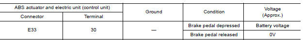
Is the inspection result normal?
YES >> Replace ABS actuator and electric unit (control unit). Refer to BRC "Removal and Installation".
NO >> GO TO 3
3.CHECK STOP LAMP SWITCH CIRCUIT FOR OPEN
- Disconnect stop lamp switch connector.
- Check continuity between ABS actuator and electric unit (control unit)
connector E33 terminal 30 and stop
lamp switch connector E13 (with CVT) or E57 (with M/T) terminal 2.

Is the inspection result normal?
YES >> GO TO 4.
NO >> Repair or replace as necessary.
4.CHECK STOP LAMP SWITCH CIRCUIT FOR SHORT
Check continuity between ABS actuator and electric unit (control unit)
connector E33 terminal 30 and ground.
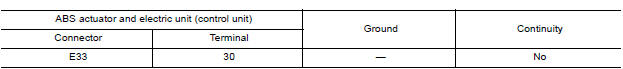
Is the inspection result normal?
YES >> Replace stop lamp switch.
NO >> Repair harness or connectors.
 C1115 ABS Sensor [abnormal signal]
Other materials:
Precautions when starting and driving
WARNING
Do not leave children or adults who
would normally require the assistance
of others alone in your vehicle. Pets
should also not be left alone. They
could accidentally injure themselves or
others through inadvertent operation of
the vehicle. Also, on hot, sunny days,
tempera ...
U0155 Lost communication (IPC)
Description
CAN (Controller Area Network) is a serial communication line for real-time
application. It is an on-vehicle multiplex
communication line with high data communication speed and excellent malfunction
detection ability.
Many electronic control units are equipped onto a vehicle, and ...
Categories
- Manuals Home
- Nissan Versa Owners Manual
- Nissan Versa Service Manual
- Video Guides
- Questions & Answers
- External Resources
- Latest Updates
- Most Popular
- Sitemap
- Search the site
- Privacy Policy
- Contact Us

0.0099