Nissan Versa (N17): Bluetooth voice signal circuit
Diagnosis Procedure
Regarding Wiring Diagram information, refer to AV "Wiring Diagram".
1.CHECK BLUETOOTH VOICE SIGNAL CIRCUIT CONTINUITY
1. Turn ignition switch OFF.
2. Disconnect audio unit connector M47 and Bluetooth control unit connector B33.
3. Check continuity between audio unit connector M47 and Bluetooth control
unit connector B33.
4. Check continuity between audio unit connector M47 and ground.
Is inspection result normal?
YES >> GO TO 2.
NO >> Repair or replace harness or connectors.
2.CHECK BLUETOOTH VOICE SIGNAL GROUND CIRCUIT CONTINUITY
Check continuity between audio unit connector M47 and Bluetooth control unit
connector B33.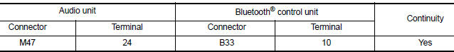
Is inspection result normal?
YES >> GO TO 3.
NO >> Repair or replace harness or connectors.
3.CHECK BLUETOOTH VOICE SIGNAL
1. Connect audio unit connector M47 and Bluetooth control unit connector B33.
2. Turn ignition switch to ACC.
3. Press  switch.
4. Check signal between the terminals of audio unit connector M47.
Is the inspection result normal?
YES >> Replace Bluetooth control unit. Refer to AV "Removal and Installation".
NO >> Replace audio unit. Refer to AV "Removal and Installation".
 Rear door speaker
Diagnosis Procedure Regarding Wiring Diagram information, refer to AV "Wiring Diagram". 1.CONNECTOR CHECK Check the audio unit and speaker connectors for the following: Proper conne ...
Bluetooth control signal circuit
Diagnosis Procedure Regarding Wiring Diagram information, refer to AV "Wiring Diagram". 1.CHECK CONTROL SIGNAL CIRCUIT CONTINUITY 1. Turn ignition switch OFF. 2. Disconnect Bluetooth con ...
Other materials:
Readiness for inspection/maintenance (I/M) test
Due to legal requirements in some states and
Canadian Provinces, your vehicle may be required
to be in what is called the "ready condition"
for an Inspection/Maintenance (I/M) test of
the emission control system.
The vehicle is set to the "ready condition" when it
is driven through certain d ...
P0731 1GR Incorrect ratio
Description
This malfunction is detected when the A/T does not shift into 1GR position as
instructed by TCM. This is not
only caused by electrical malfunction (circuits open or shorted) but by
mechanical malfunction such as control
valve sticking, improper solenoid valve operation, etc.
DTC ...
Categories
- Manuals Home
- Nissan Versa Owners Manual
- Nissan Versa Service Manual
- Video Guides
- Questions & Answers
- External Resources
- Latest Updates
- Most Popular
- Sitemap
- Search the site
- Privacy Policy
- Contact Us

0.0098