Nissan Versa (N17): B261A Push-button ignition switch
DTC Logic
DTC DETECTION LOGIC

DTC CONFIRMATION PROCEDURE
1. PERFORM SELF DIAGNOSTIC RESULT
1. Press the push-button ignition switch under the following conditions, and wait for at least 1 second.
- CVT selector lever is in the P (park) or N (neutral) position.
- Release the brake pedal.
2. Perform self diagnostic result.
Is DTC B261A detected?
YES >> Refer to PCS "Diagnosis Procedure".
NO >> Inspection End.
Diagnosis Procedure
Regarding Wiring Diagram information, refer to PCS "Wiring Diagram".
1. CHECK PUSH-BUTTON IGNITION SWITCH OUTPUT SIGNAL (PUSH-BUTTON IGNITION SWITCH)
1. Disconnect push-button ignition switch connector.
2. Check voltage between push-button ignition switch connector M25 terminal 8
and ground.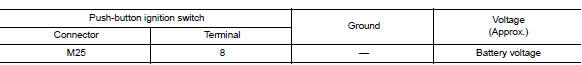
Is the inspection result normal?
YES >> GO TO 2.
NO >> GO TO 4.
2. CHECK IGNITION SWITCH OUTPUT SIGNAL (IPDM E/R)
Check voltage between IPDM E/R connector E47 terminal 81 and ground.
Is the inspection result normal?
YES >> GO TO 3.
NO >> Replace IPDM E/R. Refer to PCS "Removal and Installation".
3. CHECK PUSH-BUTTON IGNITION SWITCH CIRCUIT (IPDM E/R)
1. Turn ignition switch OFF.
2. Disconnect IPDM E/R connector E47 and BCM connector M98.
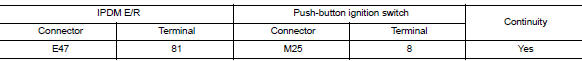
3. Check continuity between IPDM E/R connector E47 terminal 81 and
push-button ignition switch connector
M25 terminal 8.
4. Check continuity between IPDM E/R connector E63 terminal 38 and ground.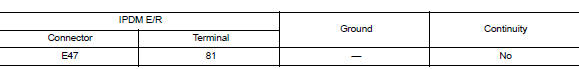
Is the inspection result normal?
YES >> Refer to GI "Intermittent Incident".
NO >> Repair or replace harness or connectors.
4. CHECK IGNITION SWITCH OUTPUT SIGNAL (BCM)
Check voltage between BCM connector M98 terminal 76 and ground.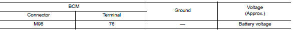
Is the inspection result normal?
YES >> GO TO 5.
NO >> Replace BCM. Refer to BCS "Removal and Installation".
5. CHECK PUSH-BUTTON IGNITION SWITCH CIRCUIT (BCM)
1. Turn ignition switch OFF.
2. Disconnect BCM connector M98 and IPDM E/R connector E47.
3. Check continuity between BCM connector M98 terminal 76 and push-button
ignition switch connector
M25 terminal 8.

4. Check continuity between BCM connector M98 terminal 76 and ground.
Is the inspection result normal?
YES >> Refer to GI"Intermittent Incident".
NO >> Repair or replace harness or connectors.
 B2618 BCM
Other materials:
Front oil seal
FRONT OIL SEAL : Removal and Installation
REMOVAL
1. Remove the following parts.
Remove wheel and tire.
Front fender protector (RH).
Drive belt.
Crankshaft pulley.
2. Remove front oil seal with ...
Differential side oil seal
Exploded View
1. Transaxle assembly 2. Differential side oil seal (left side) 3.
Differential side oil seal (right side)
Front Genuine
NISSAN Matic S ATF
Removal and Installation
NOTE:
When removing components such as hoses, tubes/lines, etc., cap or plug openings
to prevent fluid fr ...
Categories
- Manuals Home
- Nissan Versa Owners Manual
- Nissan Versa Service Manual
- Video Guides
- Questions & Answers
- External Resources
- Latest Updates
- Most Popular
- Sitemap
- Search the site
- Privacy Policy
- Contact Us

0.0079