Nissan Versa (N17): Adjustment of steering angle sensor neutral position
Description
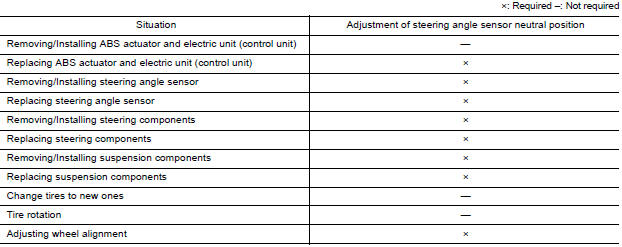
Refer to the table below to determine if adjustment of steering angle sensor neutral position is required.
Work Procedure
ADJUSTMENT OF STEERING ANGLE SENSOR NEUTRAL POSITION
CAUTION: To adjust neutral position of steering angle sensor, make sure to use CONSULT.
(Adjustment cannot be done without CONSULT).
1.ALIGN THE VEHICLE STATUS
Stop vehicle with front wheels in straight-ahead position.
>> GO TO 2
2.PERFORM THE NEUTRAL POSITION ADJUSTMENT FOR THE STEERING ANGLE SENSOR
- On the CONSULT screen, touch "WORK SUPPORT" and "ST ANG SEN ADJUSTMENT" in order.
- Touch "START".CAUTION:Do not touch steering wheel while adjusting steering angle sensor.
- After approximately 10 seconds, touch "END".
NOTE: After approximately 60 seconds, it ends automatically.
- Turn ignition switch OFF, then turn it ON again.
CAUTION: Be sure to perform above operation.
>> GO TO 3
3.CHECK DATA MONITOR
- Run vehicle with front wheels in straight-ahead position, then stop.
- Select "DATA MONITOR". Then make sure "STR ANGLE SIG" is within 0+-2.5.
Is the steering angle within the specified range?
YES >> GO TO 4
NO >> Perform the neutral position adjustment for the steering angle sensor again, GO TO 1
4.ERASE THE SELF-DIAGNOSIS MEMORY
Erase the self-diagnosis memory of the ABS actuator and electric unit (control unit) and ECM.
- ABS actuator and electric unit (control unit): Refer to BRC "CONSULT Function (ABS)".
- ECM: Refer to EC "CONSULT Function".
Are the memories erased?
YES >> Inspection End
NO >> Check the items indicated by the self-diagnosis.
DTC/CIRCUIT DIAGNOSIS
 Diagnosis and repair work flow
Work Flow OVERALL SEQUENCE DETAILED FLOW 1.COLLECT INFORMATION FROM THE CUSTOMER Get detailed information from the customer about the symptom (the condition and the environment when the in ...

Other materials:
U0101 can comm circuit
Description
CAN (Controller Area Network) is a serial communication line for real time
application. It is an onvehicle multiplex
communication line with high data communication speed and excellent error
detection ability. Many electronic
control units are equipped onto a vehicle, and each con ...
Unexpected pedal reaction
Diagnosis Procedure
1.CHECK BRAKE PEDAL STROKE
Check brake pedal stroke. Refer to BR "Inspection and Adjustment".
Is the stroke too big?
YES >>
Bleed air from brake line and hose. Refer to BR "Bleeding Brake System".
Check brake pedal, brake booster, and master cy ...
Categories
- Manuals Home
- Nissan Versa Owners Manual
- Nissan Versa Service Manual
- Video Guides
- Questions & Answers
- External Resources
- Latest Updates
- Most Popular
- Sitemap
- Search the site
- Privacy Policy
- Contact Us

0.0094